

RESOURCES - PUBLICATIONS
Calibrating Ride-on Pesticide Sprayers and Fertilizer Spreaders
Keys to Application Accuracy
Aaron Patton, Turfgrass Extension Specialist, Purdue University
Fred Whitford, Coordinator, Purdue Pesticide Programs
Dan Weisenberger, Turf Research Agronomist, Purdue University
Glenn Hardebeck, Manager, W.H. Daniel Turfgrass Research and Diagnostic Center, Purdue University
Jon Trappe, Graduate Turf Research Assistant, Purdue University
Kevin Leigh Smith, Editor, Purdue Agricultural Communication
Contents
The Popularity of Ride-on Sprayers and Spreaders. ------------------------------- 4
The Importance of Calibration. ----------------------------------------------------------- 6
Don’t Assume Factory Calibration Is Correct. ---------------------------------------- 7
Sprayer Calibration. ------------------------------------------------------------------------ 8
Steps to Calibrate Boom Sprayers. ----------------------------------------------------- 11
Calibration Worksheet for Sprayers with Booms. ------------------------------------ 17
Steps to Calibrate Single-nozzle Boomless Sprayers. ----------------------------- 18
Calibration Worksheet for Single-nozzle Boomless Sprayers. ------------------- 22
Screen and Nozzle Evaluations . -------------------------------------------------------- 23
Field Validation of the Calibration. ------------------------------------------------------- 24
Calculating the Pesticide Rate. ----------------------------------------------------------- 27
Sprayer Accessories. ------------------------------------------------------------------------ 28
Rotary Spreader Calibration. -------------------------------------------------------------- 30
Component One: Check the Distribution Pattern. ------------------------------------ 31
Component Two: Determine the Effective Spread Width. -------------------------- 42
Component Three: Calculate the Application Rate. ---------------------------------- 44
Calibration Worksheet for Rotary Fertilizer Spreaders.------------------------------ 47
Check the Accuracy of Your Calibration.------------------------------------------------- 48
Making the Trim Pass.------------------------------------------------------------------------ 49
Using the Sprayer and Spreader at the Same Time.---------------------------------- 50
Single-nozzle Boomless Sprayer.----------------------------------------------------------- 51
Multi-nozzle Boom Sprayer.------------------------------------------------------------------ 51
Keep the Owner’s Manual.------------------------------------------------------------------- 52
Conclusion. -------------------------------------------------------------------------------------- 53
Acknowledgments .----------------------------------------------------------------------------- 55
Disclaimer .---------------------------------------------------------------------------------------- 55
As lawn care companies have greatly expanded the number of acres they manage, it has become more difficult for them to apply fertilizers and pesticides in a timely manner. While hand-gun/hose-reel sprayers and walk-behind rotary fertilizer spreaders have excellent track records, they are not practical to use on larger commercial, residential, and recreational areas.
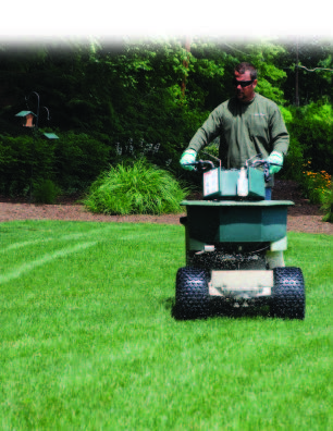
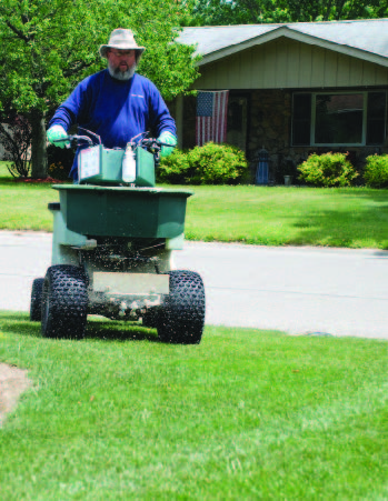
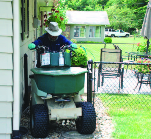
One time-saving innovation is the ride-on sprayer/spreader, which can precisely apply pesticides and fertilizers more quickly to large turf areas. Because they are small and maneuverable, professionals also can operate ride-ons on relatively small residential properties. Like any application equipment, it’s important for ride-on operators to know how to calibrate them so they can make accurate applications. This publication addresses specific procedures for separately calibrating the pesticide sprayer and the fertilizer spreader of ride-on equipment. The goal is to ensure proper application to optimize performance.
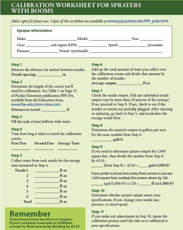
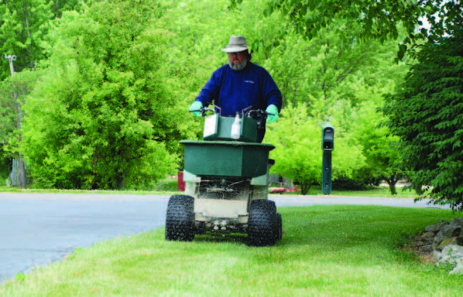
A professional applies fertilizer to a residential lawn with a ride-on sprayer/spreader.
The Popularity of Ride-on Sprayers and Spreaders
Lawn care operators and the sports turf industry adopted ride-on sprayers/spreaders quickly after they were introduced in the 1980s. Ride-on equipment offers many competitive advantages over walk- ehind spreaders and hand-guns/hose-reels.
Ride-on equipment allows operators to:
- Treat larger areas in a shorter time
- Apply fertilizers and pesticides with a single piece of equipment instead of two
- Cut chemical costs by spot-spraying liquids while simultaneously applying fertilizer
- Apply product consistently over the course of the work day because employees are less fatigued from dragging hoses or pushing spreaders
- Retain older, experienced employees
- Provide a better working environment that helps attract and keep quality technicians
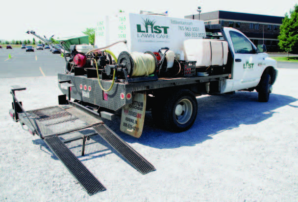
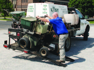
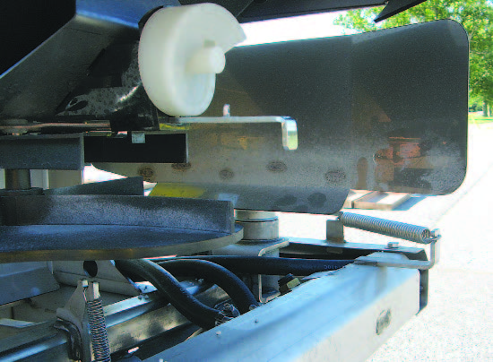
This carrier was specially built to haul ride-on sprayers. Some carriers feature passive restraint systems that improve safety and ease of unloading and loading. These carriers don’t require trailers, which means operators can haul ride-on equipment with compact vehicles that are easier to maneuver in residential neighborhoods. Typically, a vehicle needs a heavy-duty hitch to carry these units.
When operators can treat more acres in less time, their productivity increases, their labor and overhead costs decrease, and profits rise. However, ride-ons do have some disadvantages. Ride-ons require a higher initial investment, additional maintenance, and more equipment adjustments. Furthermore, it is definitely
challenging to operate ride-ons in small residential yards filled with trees, flowerbeds, shrubs, swing sets, grills, and patio furniture. It also can be more difficult to trim edges along flowerbeds.
Tight areas (such as small lawns and fenced-in areas) limit ride-on spreaders/sprayers.
The spray tanks on ride-on equipment are often small, which limits how much turf you can spray before refilling. Some pre-emergence herbicides and insecticides require high application volumes of water, which limits ride-on performance. Another concern with ride-on equipment is steep slopes. Equipment can slide down the slope and roll over, especially if they have full spray tanks or fertilizer hoppers. There also is the possibility that products can drift off-target on a windy day. Although most ride-on sprayers use nozzles to reduce drift, the nozzles produce droplets that are smaller than the large droplets from a lawn gun hose sprayer — those smaller droplets increase the risk of drift.
In today’s competitive market, ride-ons have become essential for anyone applying fertilizer and pesticides, and their performance and capabilities have overcome many of their perceived and real drawbacks. That’s probably why 70 percent of the lawn care operators in Indiana have purchased at least one ride-on sprayer/spreader. While ride-on equipment has been growing in popularity, commercial turf specialists and grounds property managers still rely on handgun/ hose-reel sprayers and walk-behind spreaders.
Each equipment type fits a unique niche in the turf management industry, and some turf areas may require both hand-gun/hose-reel sprayers and ride-on units to get a quality job done.

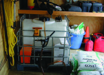
Ride-on sprayers have relatively small tanks, so many lawn care companies use large storage/supply tanks in their trucks to refill sprayers. To be effective, the products in such tanks must be mixed for use in ride-on equipment.
The Importance of Calibration
There is no substitute for having properly calibrated equipment. Whether you want to control a pest better, have healthy turf, save money, prevent off-site damage, or reduce customer complaints, investing time in calibrating equipment always pays significant dividends. Precise applications of pesticides and fertilizers allows product to function as intended. If you apply too little or too much product, it can seriously affect performance and have consequences that customers readily see.
An improperly calibrated herbicide applicator can result in poor weed control. Not applying enough fertilizer can lead to turf that is offcolor, streaked, uneven in color, and unhealthy. At the other end of the spectrum, you can injure turf if you apply more herbicide or fertilizer than the product label allows. In such cases, improper calibration means you could be violating the pesticide label.
Customers are not the only ones who see the results of poor applications. Every trip your employees make to deal with an application complaint (callback) is a trip and application that is not billable. The costs of labor, equipment, and fuel make such complimentary applications expensive. Profits increase when there are fewer callbacks.
It might be a subtle point, but improperly calibrated equipment leads to quality issues that customers, clients, or supervisors will notice. When weeds are not controlled or turf looks unhealthy, customers question the value of the service. Your truck and the flag you leave behind advertise the quality of your work.
Don’t Assume Factory Calibration Is Correct
Ride-on application equipment manufacturers provide instructions about calibrating their equipment. The instructions usually describe how much area the sprayers will treat. On new equipment, manufacturers provide an approximate calibration by equipping their sprayers with a specific nozzle to deliver a target application volume at a target application speed. If that preset output does not meet your needs (too high or low), you will have to change the speed, pressure, or nozzle type. Any modification or change you make will require recalibrating the equipment. And, as with any newly purchased equipment, you should ensure that everything is working well and double-check the manufacturer calibration values through a true calibration. It is important to realize that no two sprayers or spreaders are identical even when they are new — and they become less so as they age. That means you will need to calibrate each piece of equipment independently. You also need to precisely calibrate spreaders after you purchase them. Manufacturers provide a starting point from which to work. You will need to adjust the spreader opening and distribution pattern depending on the size of the fertilizer granule you use and the rates you apply.

Sprayer Calibration
Whether you purchase equipment new, used, recently repaired, or updated with new add-on equipment, you need to calibrate it. You also need to remember that equipment naturally wears over time, so you should recalibrate periodically. One firm rule is that you should calibrate ride-on sprayers before using them at the start of each growing season. How often you will need to check the calibration after that varies by personal preferences and amount of use. Many grounds and turf professionals calibrate them daily or weekly. These frequent calibration checks help ensure consistent application results.
Another steadfast rule is that you should always calibrate ride-on sprayers after any mechanical work is performed on them. Check nozzles for wear each time you calibrate the sprayer, and frequently clean screens. Many companies clean their screens daily. Before you calibrate your equipment, always inspect it to make sure it is in good working condition. Be sure the tires are properly inflated and the axles are properly greased.
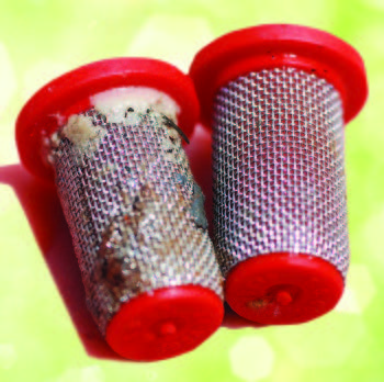
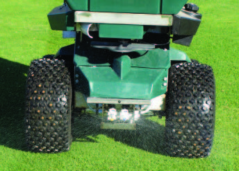
Something as simple as a partially clogged screen (left) can undermine any calibration by altering the flow of water. Clean screens (right) can help keep sprayer output consistent. Remember to clean any filters between the spray tanks and nozzles.
What You’ll Need to Calibrate Sprayers
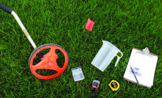
Here’s a checklist of things you’ll need to calibrate a sprayer.
Pencil
Paper
Calculator
100-foot (or longer) tape measure or measuring wheel
Marking or pin flags
A watch or cell phone that can measure time in seconds
Containers marked in ounces to collect liquid from nozzles
Calibration worksheets in this publication
There are two general ride-on sprayer designs: boom-type and boomless. A boom-type sprayer has a set of nozzles along the length of a boom. A boomless sprayer clusters a bank of different nozzles under the front center of the sprayer. This publication covers the steps for calibrating each design separately.
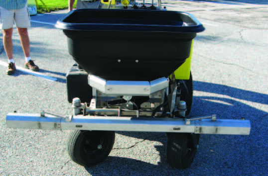

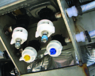
A boom-type ride-on sprayer (top) and one of the nozzles along its boom (bottom).
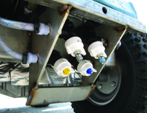
Most single-nozzle (boomless) sprayers actually have a cluster of nozzles under the front center of the sprayer. Although there are multiple nozzles, you should only use one at any time. The ability to select nozzles permits quick and accurate changes in spray width for trim and broadcasting or when changing ground speed. You must calibrate each nozzle and speed combination on the sprayer.
STEPS TO CALIBRATE BOOM SPRAYERS
There are many different methods to calibrate ride-on liquid sprayers. One of the easiest and quickest is the “ounces to gallons” method developed by Erdal Ozkan in Boom Sprayer Calibration (Ohio State University Extension publication AEX-520-92, available from Ohioline, ohioline.osu.edu). This method (which is the one used in this publication) is excellent because it greatly simplifies the math.
Before calibrating any equipment, always answer the question, “How much water do I want to apply per 1,000 square feet or acre?” Product labels often have minimum spray volume requirements per acre or 1,000 square feet. Read labels first to make sure you are applying sufficient volume. After that, follow
these 11 steps for calibrating boom sprayers.
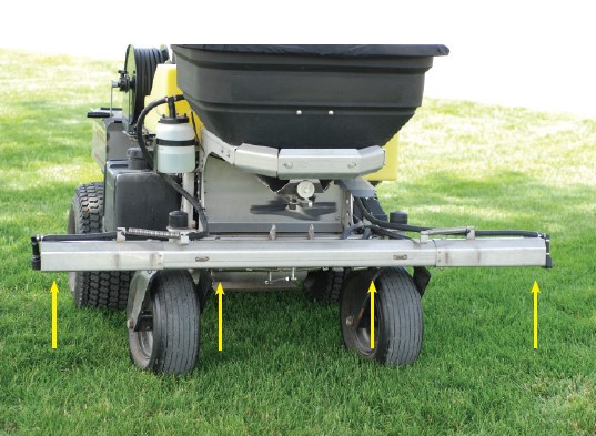
A boom-type ride-on sprayer/spreader with four nozzles. Arrows point to nozzle placement.
Step 1
Measure the distance (in inches) between nozzles. The photos on this page show a distance of 20 inches between nozzles.
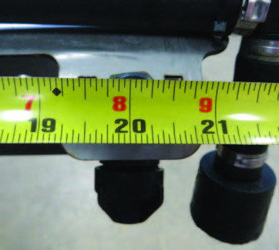

The distance between nozzles may differ between manufacturers, but for each unit the distance between nozzles should be equally spaced.
Step 2
Determine the length of the course you’ll need for calibration. Consult Table 1 to determine the distance you will need to travel for calibration. For example, if you have a ride-on sprayer with 20-inch nozzle spacing, Table 1 shows you will need a calibration course that is 204 feet long. When you establish a calibration course, pick an area that has terrain that will be similar to the turf you treat. Place a flag at the beginning of the course and another at the end. Do not set a calibration course on a hard surface because the speed will be different than on turf.

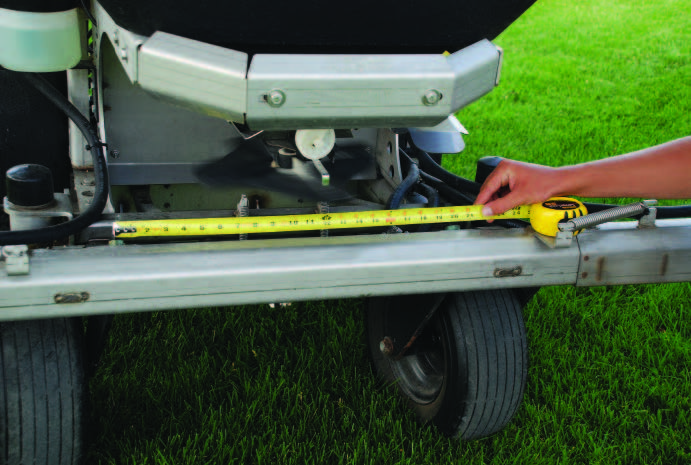
Use a measuring tape or wheel to measure the length of a calibration course.

Step 3
Fill the tank at least halfway with water to provide a realistic weight for the test. At this stage, you will not use any pesticides.
Step 4
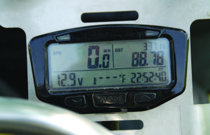
Time how long it takes to travel the calibration course. Have a second person use a stopwatch to time how long it takes to cover the calibration distance from the beginning flag to the ending one. Be certain to cover the entire calibration course at the speed you will be travelling when treating turf. Keep the speed constant from the time you drive over the start line until you pass the finish line. Repeat the process by going back over the course in the opposite direction. Add both course completion times together and divide by 2 to get an average speed of travel. If the sprayer has a speedometer, record the speed (in MPH) when running the calibration course. Otherwise, record the gear and engine rpm so you can repeat the speed of the sprayer
during actual applications. You can use MPH or the gear/engine RPM for this — one is not necessarily better than the other.
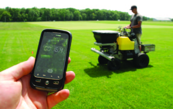
If you don’t have a stopwatch, you can use a cell phone or other device to keep time during calibration.
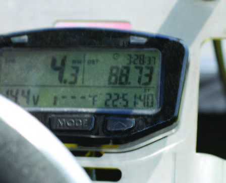
If your sprayer has a speedometer, record the speed that was used during the calibration.
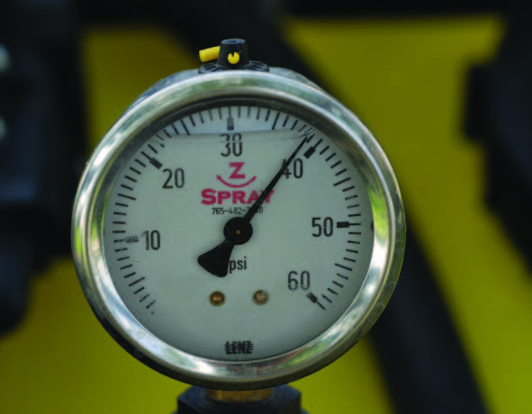
Record the nozzle pressure used during the initial calibration steps. Although changing speed or nozzle size is the best way to adjust your calibration volume, you can also modify nozzle pressure on some models to make small adjustments to output.
Step 5
Collect water from each nozzle for the same amount of time (average time) it took you to travel the calibration course in Step 4. Collect the water, not while the sprayer is moving, but when it is parked and running at the same engine speed (RPM) so the spray pressure is the same that it was used on the calibration course. For example, if it took 32.5 seconds to cover the calibration course, collect water for 32.5 seconds. Collect water twice and divide by 2 to get the average output. Also be sure to write down the nozzle type and operating pressure you used for the test run. Record the output (in fluid ounces) from each nozzle. Use a measuring container that has printed markings for each fluid ounce — ideally it should have markings for each half-ounce, too. For example, the four nozzles in the photos on this page delivered 13.5, 16, 16, and 14.5 fluid ounces.
If your container measures in milliliters, simply divide the amount of water you collect by 29.57 to convert the metric output to the more familiar fluid ounces.
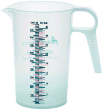
Quart and pint measuring containers that have printed markings for each whole and half fluid ounce are ideal for calibration measurements.
Calculate the average number of fluid ounces delivered from each nozzle for the length of time it took to travel the calibration course.

Step 6
Add up the total amount of water you collect from the sprayer and divide that amount by the number of nozzles. This will give you the average output per nozzle. For example, if the sprayer has four nozzles that applied 13.5, 16, 16, and 14.5 fluid ounces, then the average output is 15 fluid ounces per nozzle:
13.5 + 16 + 16 + 14.5 = 60
60 ÷ 4 = 15
Step 7
Check the nozzle output. If any nozzle varies by more or less than 10 percent of the average output, then there may be a problem with the nozzle. If none of the nozzles varies by more than 10 percent, proceed to Step 8. If a nozzle has a lower than average output, then it may be plugged or have a plugged screen. A nozzle with a higher than average output is likely worn out and needs to be replaced. After you clean any screens or replace any nozzles, go back to Step 5 and rerun the volume check on all the nozzles. It is important to check all nozzles again in case your adjustments affected the output of the other nozzles. Recalculate the average nozzle output, and double-check that all nozzles are within the 10 percent of the average output. If half the nozzles are out of range, replace the entire set.
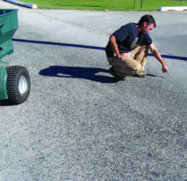
In the example above, the average output was 15 ounces, so 10 percent is 1.5 fluid ounces. Subtract and add 1.5 to the average to get the acceptable range: 13.5 to 16.5 ounces. Because the output from each nozzle in our example is within this range, none of them need to be replaced yet. Make a pass over pavement to double-check that the spray pattern appears uniform. Spray the pavement at the same speed (gear), engine RPM, and pressure you used while going over the calibration course. Watch the pavement dry and observe any irregularities that may exist in the spray pattern.
Step 8
Determine the sprayer’s output in gallons per acre. This should be easy because of the conversion factors that were used in Step 2 to determine the length of the calibration course. The average nozzle flow measured in fluid ounces is equal to the sprayer’s output in gallons per acre. This helps make the math easy. For example, the average nozzle output of 15 fluid ounces over the application course is equal to 15 gallons of spray per acre for the entire sprayer.
Step 9
If you need to determine sprayer output for 1,000 square feet, then divide the gallons of water per acre from Step 8 by 43.56 (43,560 square feet = 1 acre). For example, divide 15 by 43.56 to get 0.34 gallon per 1,000 square feet.
Step 10
Determine whether the sprayer output meets your specifications. If it does, then the equipment is calibrated and ready to be put in service. If the amount of water per acre or per 1,000 square feet is higher or lower than what you wanted, then you will need to adjust the nozzle pressure (small adjustment), nozzle size (large adjustment), or speed (medium adjustment).
Step 11
If you make any adjustments in Step 10, repeat the calibration process until the ride-on is calibrated to your specifications.
STEPS TO CALIBRATE SINGLE-NOZZLE BOOMLESS SPRAYERS
This single-nozzle boomless ride-on sprayer has four nozzles, but it only uses one at a time.
Each single-nozzle boomless sprayer has a cluster of nozzles under the front center of the unit, but it only uses one at a time. Calibrate each nozzle for the gear it will operate in, because speed affects the amount of water applied per acre. PermaGreen® style sprayers can have as many as four combinations that affect the
spray volume (two FloodJet® nozzles plus two speeds). There are a similar number of combinations that affect the spray volume of the trim nozzles (two flat-fan nozzles plus two speeds). Whichever combination is used, each will need to be calibrated.
The steps you take to calibrate single-nozzle boomless sprayers are similar to those of boom sprayers and require the same supplies described on Page 9. As with boom sprayers, your goal is to determine how much water you want to apply over an acre or over 1,000 square feet.
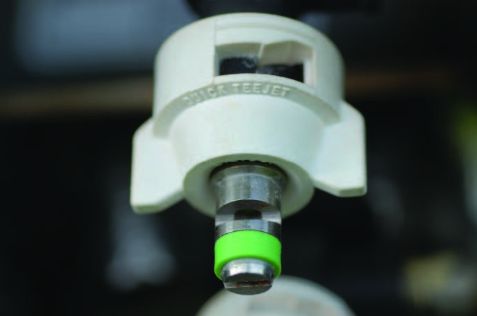
Two common spray nozzle types for single-nozzle ride-on sprayers are a FloodJet® (top), which is used to apply material over larger areas, and a tapered flat-fan nozzle (bottom), which is used for trim (narrow band) passes.
Step 1
Select the nozzle you want to use.
Step 2
Measure a calibration course on turf that is 100 feet long. As with boom sprayers, pick an area that has terrain that is similar to the turf you treat. Place a flag at the beginning of the course and another at the end. Do not set a calibration course on a hard surface because the speed will be different than on turf.
Step 3
Fill the tank at least halfway with water to provide a realistic weight for the test. At this stage, you will not use any pesticides.
Step 4
Time how long it takes to travel the calibration course. Cross the start and finish lines at the same speed (gear and RPM) you will use when you treat turf. Keep the speed constant from start to finish. Repeat the process by going back over the course in the opposite direction. Add both course completion times together and divide by 2 to get the average time it took to travel 100 feet. For example, it took a ride-on an average of 13.6 seconds to travel the 100-foot course in high gear at 3,450 RPM.
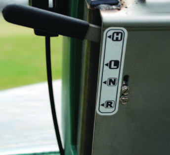
Adjust your travel speed and calibration by changing from low- to high-gear (or vice versa). Always note your engine RPM while calibrating.

Step 5
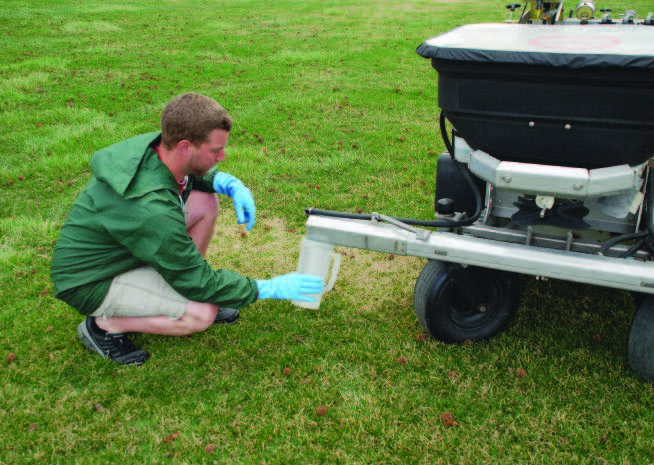
Collect water from the nozzle for the same amount of time (average) it took you to travel the calibration course in Step 4. Collect the water, not while the sprayer is moving, but when it is parked and running at the same engine speed (RPM) so the spray pressure is the same that was used on the calibration course. For
example, if it took 13.6 seconds to cover the calibration course, collect water for 13.6 seconds. Record the amount of water you collect (in fluid ounces). Use a measuring container that has printed markings for each fluid ounce - ideally it should have markings for each halfounce, too. Collect water twice and divide by 2 to get the average output. For example, for one calibration we collected 22 and 23 fluid ounces in 13.6 seconds. The average output was 22.5 fluid ounces.
Collect water for the same period it took you to cover the calibration course.
Step 6
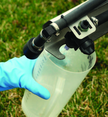
Check the nozzle distribution pattern. Do this while the sprayer is parked over pavement and spraying at the same engine RPM and pressure from Step 4. Adjust the nozzle if the pattern is uneven.
Step 7
Determine the effective width of the spray pattern. To do this, fill the tank only with water and make a pass over pavement. Spray the pavement using the speed (gear), engine RPM, and pressure you used over the calibration course, and then watch the pavement dry. The edge of the spray pattern (where little water was applied) will dry and disappear quickly. Some call this the feathered edge.
Check the nozzle distribution pattern while the sprayer is parked and spraying at the same RPM and pressure as during the calibration run. This nozzle has a uniform spray pattern.
To determine the effective width, you want to measure where the nozzle applies most of the water. Measure the width (in feet) where most of the water is applied and exclude the feathered edge. This is the effective spray width.
Locate each edge of the spray pattern where the pavement is consistently wet. Measure from edge to edge to get the effective spray width.
In our example, we measured an effective spray width of 7 feet. That means there should be 7 feet between passes.
Step 8
Calculate how many square feet were treated. To do this, multiply the effective spray width (from Step 7) by 100 (the length of the calibration run). That will give you the area (in square feet) that you treated. For example, if the effective spray width is 7 feet, then the sprayer treated 700 square feet.
Step 9
Calculate the volume applied per 1,000 square feet. This requires a two-step process:
(a) determine the ounces of water per square foot, and then (b) determine the ounces of water per 1,000 square feet.
a. Determine the ounces of water per square foot. Take the average fluid ounces you collect from the nozzle in Step 5 and divide it by the total area treated in Step 8.
For example: 22.5 fl oz ÷ 700 ft2 = 0.03214 fl oz/ft2
b. Determine the ounces of water per 1,000 square feet. Multiply the fluid ounces per square foot by 1,000.
For example: 0.03214 fl oz/ft2 x 1,000 = 32.14 fl oz/1,000 ft2
Step 10
Calculate the number of gallons applied per 1,000 square feet or per acre. This also is a two-step process.
a. Determine the number of gallons applied per 1,000 square feet. Divide the fluid ounces per 1,000 square feet (from Step 9b) by 128. Remember, there are 128 fluid ounces in one gallon.
For example: 32.14 fl oz/1,000 ft2 ÷ 128 = 0.25 gal (1 qt)/1,000 ft2
b. Determine the number of gallons applied per acre. Multiply the number in Step 10a by 43.56. Remember, there are 43,560 square feet in an acre.
For example: 0.25 gal/1,000 ft2 x 43.56 = 10.9 gals/A
Step 11
Determine whether the sprayer output meets your specifications. If it does, then the equipment is calibrated and ready to be put in service. If it does not meet your expectations, adjust the nozzle pressure (if it is an option on your sprayer) or speed (gear and RPM), or replace nozzles. Note: changing nozzles or speed is the best way to change sprayer output; increasing pressure increases the possibility of drift.
To adjust the effective spray width, reposition the nozzle to widen or narrow the pattern, and/or adjust nozzle pressure (if it is an option on your sprayer). Any change will require you to recalibrate the unit.
Step 12
Repeat the calibration process if any action is taken in Step 11.

You can adjust the pressure from 20 to 30 psi on the diaphragm-type antidrip valve on Permagreen® models. This slightly increases the effective spray width.

SCREEN AND NOZZLE EVALUATIONS
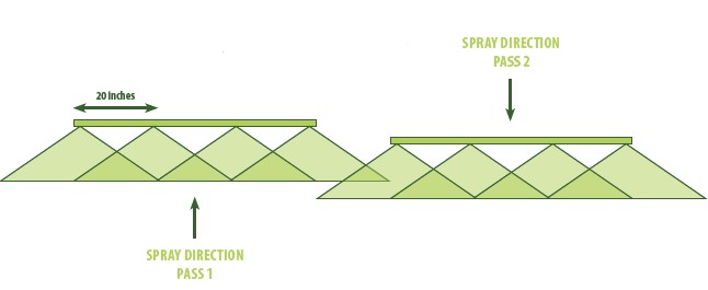
For boomless sprayers, it is a good idea to change the nozzle once a year or if the spray pattern is no longer uniform. The single-nozzle design of a boomless sprayer, gives it a distribution that is very similar to a rotary fertilizer spreader. The highest amount of spray is applied directly in front of the sprayer with less to the sides. To achieve a uniform application, you must spray on your current pass back to the effective spray edge of your previous pass (see Page 20). One reason to change a nozzle is when it becomes worn from use. If a nozzle on a boom sprayer varies by more than 10 percent from the average spray output, then replace it.
Sometimes, changing all the nozzles on a boom sprayer might be an advantage when you want a lower or higher output. You also can change the output of a boom sprayer by changing the ride-on’s speed and, to a lesser degree, its pressure. Spray nozzles have a uniform coding system that manufacturers use to describe the spray droplet size, spray angle, and opening size.
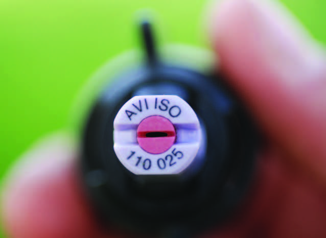
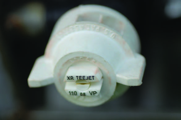
A nozzle from a ride-on sprayer with a boom.
For example, if you have a nozzle coded AVI ISO 110025, then you know the following information: • AVI: This indicates it is an air induction spray nozzle that uses the Venturi system. • ISO: This indicates that the manufacturer used the International Standards Organization (ISO) colorcoding system to indicate the nozzle’s opening size. For example, a red nozzle typically has the same opening size regardless of who manufactured it.
• 110: This number tells you that the spray angle is 110 degrees. When you replace nozzles, always choose nozzles with the same spray angle because the angle is specific to your sprayer’s nozzle spacing and boom height.
• 025: This indicates the nozzle’s spray output (in gallons per minute at 40 psi). In this case, 0.25 gallon per minute. To change your sprayer output, you can use the nozzle coding system to help select nozzles that have different opening sizes, spray patterns, or output per acre. The system allows you to select the appropriate nozzle whether you have a boom-type or boomless sprayer.
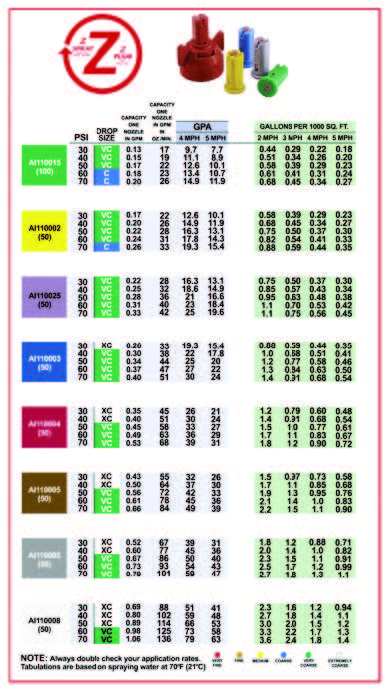
Nozzle manufacturers often provide calibration charts with nozzle information online. Some sprayer models come with this information.
FIELD VALIDATION OF THE CALIBRATION
After you do the hard part (calibrating the sprayer), you need to put the ride-on sprayer to the test to make sure that your calibration works under field conditions.
To complete a field validation:
1. Predict how many acres you expect to cover
2. Determine the width between passes
3. Validate the calibration
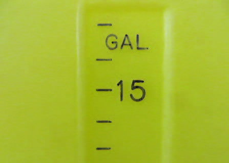
Just because a tank says it holds a certain volume, doesn’t mean it does. Always check tank capacities for accuracy. For more information, see Measuring Pesticides: Overlooked Steps To Getting the Correct Rate (PPP-96) available from the Purdue Extension Education Store: (888) EXT-INFO (396-4636).
Predict How Many Acres You Expect to Cover
First, calculate how many acres a given spray tank will cover. Use the same formula whether the sprayer has booms or is boomless.
[Tank capacity (gals)] / [gals/A from Step 8 (boom) or Step 10b (boomless)] = acres the spray tank should cover
A boom sprayer example: say you have a boom sprayer that has an 18-gallon tank, and its predicted output is 15 gallons per acre (based on Step 8 of the calibration process). You should have enough product in the sprayer tank to cover 1.2 acres (52,272 square feet).
[18 gals] / [15 gals/A] = 1.2 acres product in tank should cover
1.2 A x 43,560 = 52,272 ft2
A boomless sprayer example: say you have a sprayer with a 12-gallon tank, and its predicted output is 10.9 gallons per acre (based on Step 10b of the calibration process). You should have enough product in the sprayer tank to cover 1.1 acres (47,956 square feet).
[12 gals] / [10.9 gals/A] = 1.1 acres product in tank should cover
1.1 A x 43,560 = 47,916 ft2
Determine the Width Between Passes
To spray an area uniformly you have to have the correct distance between passes. For a boom sprayer, the effective spray width is the distance between nozzles multiplied by the number of nozzles. For example, if you have a boom sprayer with four nozzles that are spaced 20 inches apart, the sprayer has an effective spray width of 80 inches (6.7 feet).
To spray an area uniformly, you will need to make application passes that are 6.7 feet apart. That is, make the center of your wheel tracks 6.7 feet apart on each pass to make a uniform application. Another way to look at this is that the spacing between the nozzles at the end of the boom should always match the spacing of the nozzles along the boom. For example, let’s say you have a boom with nozzles spaced 20 inches apart. Space your passes so that the nozzle on the end of the boom of the current pass will travel over a spot that is 20 inches away from where the nozzle on the end of the boom was during the previous pass.
Flat fan pattern nozzles with a 110˚ pattern angle. This four nozzle boom with individual nozzles spaced 20 inches apart has an 80 inch (4 x 20 in = 80 in) application pattern (width). Check the nozzle information for your type to determine the overlap required. Flat fan nozzles require 50% overlap for even applications.
Experienced applicators will be able to approximate this through practice. Sometimes, you can identify where you have already sprayed by the wetness of the leaf. New applicators can practice by spraying turf with a spray dye indicator in the tank. The dye will help you see where you have sprayed. A spray foam marker may also be useful (see Page 28). For a boomless sprayer, use the effective spray width measured in Step 7 (Page 20). For example, say you have a sprayer with an effective spray width of 7 feet. To spray an area uniformly, you will need to make application passes that are 7 feet apart from one another. That is, make the center of your wheel tracks 7 feet apart on each pass to make a uniform application. Again, experienced applicators will be able to approximate this through practice. Just like with a boom sprayer, you can look for wet leaves or use a spray dye indicator.
Validate the Calibration
A simple way to validate a calibration is to run the sprayer over turf that you know is 50,000 square feet (a little larger than 1 acre). Many ride-on sprayers are equipped with standard capacity tanks that will treat approximately 50,000 square feet or a little more than an acre. Use 50,000 square feet of turf that is flat and contains no obstructions such as trees or buildings. Spray the acre with only water, and then check how much remains in the spray tank. What is left should correspond to what you had predicted from your calibration. For example, if your tank is calibrated to cover 50,000 square feet, then your tank should be empty (or nearly empty) by the time you finish covering that area. If a small amount of water remains in the tank (or if you run out just before you finish treating the area, then your calibration is accurate. However, if there is a lot of water in your spray tank or you run out way too soon, then there may be a problem.
If the spray tank has more water than expected, then the causes might be that you:
• Went faster than you did over the calibration course
• Did not overlap your passes
• Used a lower pressure than you used over the calibration course
• Made a math error in your calibration steps If you ran out of water long before expected, then the causes might be that you:
• Went slower than you did over the calibration course
• Overlapped your passes too much
• Used a higher pressure than you used over the calibration course
• Made a math error in your calibration steps
Use the Right Application Volume
CALCULATING THE PESTICIDE RATE
Here are some examples to illustrate how to calculate the pesticide rate for ride-on equipment.
Boom Sprayer
Let’s say you have a calibrated boom sprayer that has an 18-gallon capacity that applies 0.34 gallon per 1,000 square feet (step 9, Page 16). The label for the pesticide you are applying calls for 1.1 fluid ounces per 1,000 square feet. How much chemical should you add to the 18-gallon tank?

Boomless Sprayer
Let’s say you have a boomless sprayer that has two 6-gallon tanks and applies 0.25 gallon per 1,000 square feet (Step 10b, Page 21). The label for the pesticide you are applying calls for 1.1 fluid ounces per 1,000 square feet. How much chemical should you add to fill up 12 gallons?
Use the same formula provided for boom sprayers above:
Ride-on sprayers have relatively small tanks, so many lawn care companies keep large tanks with product on their trucks that they use to refill sprayers. If you do that, make sure your tank contains pesticides that have been mixed exclusively for use in your ride-on sprayer. The application volume for a ride-on is different than the application volume for a hose-reel/lawn gun. A ride-on sprayer delivers 12 to 20 gallons of spray volume per acre, and lawn guns typically deliver more than 60 gallons of spray volume per acre. Failing to mix the supply tank to match the application volume called for by the ride-on sprayer will yield poor results.
This boom sprayer has a foam marking system that marks the edges of the spray pattern.
SPRAYER ACCESSORIES
Manufacturers constantly add new accessories for ride-on sprayers. For example, you can equip your ride-on sprayer with a foam marking system that allows you to see the outside edges of what you have sprayed. Such systems allow you to make more uniform applications because you can see where you need to overlap. Many ride-on sprayers have speedometers to help you keep the unit moving at a more uniform speed over large turf areas. You can also add a hose and lawn gun attachment to reach small lawns and tight places. Spray rate controllers also are available to help maintain a constant spray output during small changes in travel speed. These controllers modulate the pump to increase pressure when you speed up and to decrease pressure when you slow down.
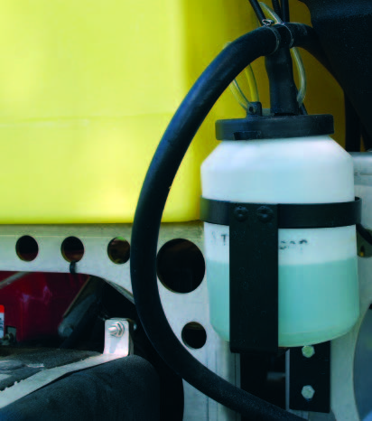
A foam marking system comes with a tank to fill with foamer to mark the edges of your spray pattern.
Speedometers can help you maintain a constant speed.
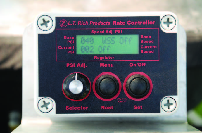
A rate controller can help you maintain a constant application rate despite changes in travel speed.
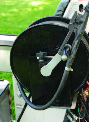
A hose reel attachment for small lawns, tight places, and spot treatments.
Safety and PPE
Many applicators have been using ride-on units since the 1990s safely; however, operators have been injured and even killed while operating these units. In many cases the injuries occurred while operating on slopes. Ride-on equipment can have a higher center of gravity when loaded and, depending on the model, can be physically difficult to maneuver on slopes. Other operators have been hurt while loading ride-on units onto trailers or into vehicles. Exercise caution and always follow manufacturer safety precautions. You also should use proper personal protective equipment (PPE) while operating these units. In general, most state departments of agriculture do not differentiate between pesticide applications made with lawn guns and those made with ride-on units. Whether filling equipment, making applications, or calibrating a unit,
you must use the minimum PPE noted on the pesticide label.
Rotary Spreader Calibration
A properly calibrated spreader is essential equipment for all professional turfgrass managers. Overapplying fertilizers wastes money and can injure turf and nearby ornamental plants. Underapplying fertilizers can lead to customer complaints when turf quality declines. You can avert these sorts of problems by calibrating your ride-on spreaders to deliver products uniformly at the proper rates. At a minimum, you should calibrate a spreader each time you use a new product, even if that product has the same nutrient content, size guide number (SGN), or amount of active ingredient as a previous product. The main reason to recalibrate is the important influence that granule size and particle density has on flow through the spreader opening. It’s
also important to note that, just like a sprayer, changing your travel speed (gear) requires you to recalibrate the fertilizer spreader.
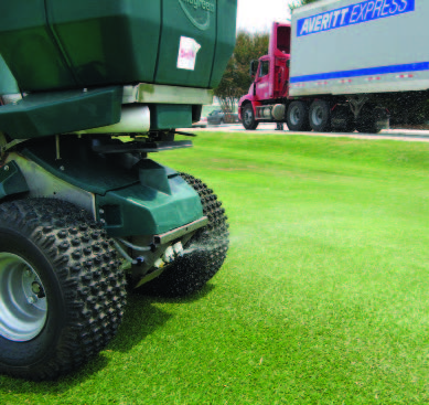
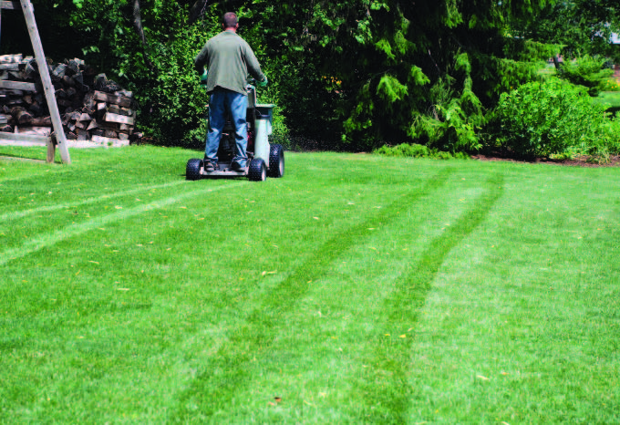
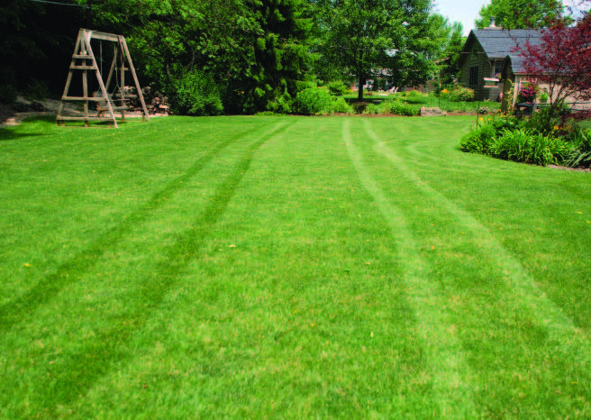
This applicator is throwing fertilizer back toward his previous pass (wheel-towheel) at a distance that loosely approximates his effective spread width.
To make uniform applications with rotary ride-on spreaders, you must check for proper distribution and then determine your effective spread width. The distribution pattern is important because a rotary spreader must be adjusted for each product to make sure it throws equal amounts of the product to the left and to the right. The effective spread width is important because with a rotary spreader you must overlap the product to achieve a uniform application. This overlap is critical for uniform fertilizer distribution, because the highest rate of product is placed directly in front of the spreader while a lesser amount is placed to the right and left.
Before calibrating your spreader, use this checklist to make sure it is in good working condition. Before calibrating, make sure that the:
Tires are properly inflated
Axles are greased
Spreader hopper and impeller are clean
Screen and agitation bar in the hopper are clean
Adjustment knob holds its position when tightened
Gears are greased (if recommended) and teeth on the gears are present
Desired pattern adjustment is set
There are three components for calibrating ride-on rotary fertilizer spreaders:
1. Check the distribution pattern of fertilizer across the spreader swath
2. Determine the effective spread width
3. Calculate the application rate
COMPONENT ONE: CHECK THE DISTRIBUTION PATTERN
In a rotary spreader, it’s important that the spinner plate (impeller) throws equal amounts of fertilizer to the right and left. If one side gets more product than the other, then overlapping will magnify this error and result in uneven application and banding/striping.
A rotary spreader’s distribution pattern can change when granular dust builds up on the spinner (impeller). Clean the spinner on a regular basis to keep the application accurate.
Some applicators try to observe how much fertilizer the spreader throws to the sides, but it is not possible to accurately calibrate the spreader pattern this way. A more thorough check of the pattern after a visual estimate often reveals that you need to make additional adjustments. It is worth your time to spend a few extra minutes to properly adjust the pattern if your goal is to achieve uniform application. The first thing to do is make a spreader calibration kit (see Page 32).
Making Spreader Calibration Kits
To calibrate a ride-on spreader, it’s a good idea to create a kit that will help you do the job. Calibration kits are easy to make or assemble. You can use many different designs and specifications to create your working calibration kit, but each kit requires four items: (1) collection boxes or pans, (2) baffles, (3) clear tubes, and (4) a tube rack.
1.Collection boxes or pans
You can buy or make collection boxes. Cardboard boxes work well, but you can also use plastic or aluminum pans. In any case, shallow boxes with upright lips that are no more than 2 inches tall work best. If boxes are more than 2 inches tall, they may not catch all the fertilizer and will be too high for the equipment to clear. The boxes should be 1 foot (12 inches) wide. This makes it easy to determine your spread width. The length can vary between 12 and 36 inches. The longer the box, the fewer the number of passes you need to make to collect enough material to fill your tubes. The size we used for the calibration demonstrations in this publication is 12 inches wide by 36 inches long by 2 inches deep. We made ours by cutting cardboard from a large shipping box and then assembling the pieces using packing tape. We used 12-by-36-inch pieces for the bottom, and 2-inch tall strips measuring 12 and 36 inches for the sides.
These custom 1-foot by 3-feet collection boxes were made from cardboard scraps and packing tape.
You can buy similar-size boxes online. For example, item #016700 at www.papermart.com is a cardboard box that is 12 inches wide by 36 inches long by 4 inches deep. While 4 inches is too tall, you can cut off the lid and trim down the sides to make it work.
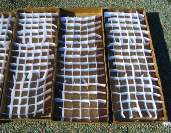
2. Baffles
Baffles will help keep fertilizer from bouncing out of the collection boxes during calibration. You can make baffles or partitions with cardstock paper. Cut the paper into strips the same height as the height of your boxes. Cut halfway through the strips at 2-inch intervals to create slits. After you make several strips this way, fit them together using the slits to make baffles.
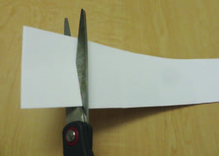
Cut cardstock paper into strips that are the same height as your collection boxes. Cut halfway through these strips at 2-inch intervals to create slits.
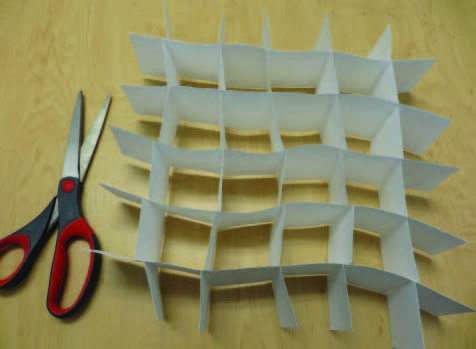
After making several strips with slits, fit the strips together using the slits to make baffles.
3. Clear tubes
There are various types of clear tubes you can use to collect fertilizer from each collection box. Test tubes, graduated cylinders, and even rain gauges work well — and they’re available from various vendors. Plastic tubes are preferable, and we suggest buying at least 50 of them so you can compare two to three calibration runs at a time. Make sure your tubes can hold 1 to 4 fluid ounces (30 to 120 milliliters/cubic centimeters). The photos on this page show a few examples of tubes you can use.
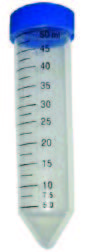
These 50-milliliter plastic centrifuge tubes are one kind of tube you can use for spreader calibration.
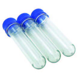
You can order Baby Soda Bottles® (also called giant test tubes) online. They hold 35 milliliters and work well for spreader calibration.
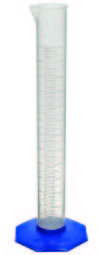
This plastic graduated cylinder is another tube option you can use for spreader calibration. Since these tubes already have a base, you won’t need a rack.
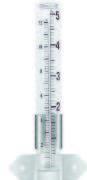
A rain gauge also works well for spreader calibration.
4. Tube racks
You can buy a rack or build a rack to hold your tubes. Make sure your racks can hold enough tubes (11 to 15) to display the results from all your collection boxes.

This test tube rack works well for displaying the tubes. A funnel is a helpful tool for pouring the fertilizer from the collection boxes into the tubes.
Follow these six steps to check your spreader’s distribution pattern.
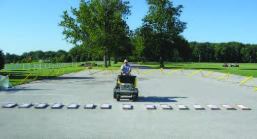
Step 1
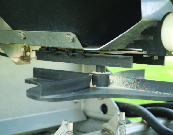
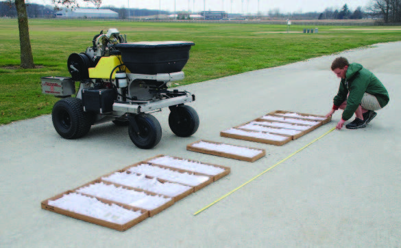
Place shallow boxes or pans side-by-side in a line that is perpendicular to the path the spreader will be traveling. Ideally, these boxes should contain dividers (baffles) to keep the fertilizer in the box and prevent it from bouncing out.

To check a spreader’s distribution pattern, place shallow boxes with baffles side-by-side in a line perpendicular to the direction the spreader will travel.
For fertilizers with small granules (SGN≤150), use 11 boxes. For fertilizers with large granules (SGN>150), use 15 boxes. SGNs are typically provided on fertilizer bags and labels. Place the collection boxes side-by-side so that you can collect granules along the entire width of the spread. It’s important to use an odd number of boxes for this test. That way, there is one box in the middle and an equal number of boxes on both sides. For example, if you use 15 boxes, there is a box in the middle, and then seven on the left and seven on the right.
You can space the boxes up to 12 inches apart depending on the impeller speed and granule size. Large granules spread farther, so space the boxes farther apart. Small granules do not spread as far, so place the boxes right next to each other. Make sure to place one box directly beneath the spot where the middle of the spreader will pass. Leave enough space between this center box and the boxes on the left and right sides for the wheels to pass. Make sure that the boxes on the outside edges are far enough out that they will collect little fertilizer — about 10 percent or less of that in the middle box.

The size guide number (SGN) indicates the size of the fertilizer granules. Fertilizer bags or product information sheets often include SGNs.
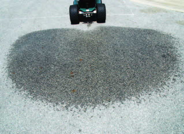
The center box is marked with an arrow. Notice the extra space on either side of the center box to allow room for the wheels. In this example, the spreader is being calibrated for a product with a large granule, so the boxes are placed about 12 inches apart to catch the granules along the entire width of the spread.
In this example, the spreader is being calibrated for a product with a small granule , so there is no space between the boxes. Closer box spacing with small granules helps you determine the effective spread width more accurately.
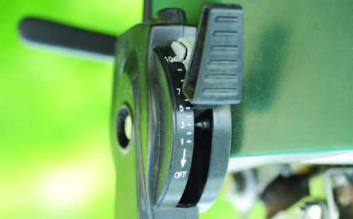
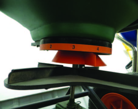
The spreader gate opening lever varies by spreader model. The settings on a PermaGreen® (top) are numbered 0 to 30, and the settings on the Z-Spray Intermediate® (right) are numbered 1 to 9.
Step 2
Choose a starting point for your rate that will be similar to your final rate setting. Most fertilizer bags do not include settings for rideon spreaders since this equipment type is still fairly new. However, some manufacturers are starting to include this information on their products. In any case, it is hard to approximate what this setting will be without previous field experience with the product. The owner’s manual for a spreader typically offers little guidance about what the proper spreader setting should be. However, you may get some valuable information if you call the spreader manufacturer’s customer support line or your local fertilizer distributor. Trial and error and advice from your peers at turf conferences and workshops will yield valuable information about how they determine their initial rate settings. Keep in mind that any information you obtain (regardless of the source) will not be exact because your equipment’s age, how it’s
operated, the product’s granule size, and the product’s flow can alter how much product the spreader actually applies. This information serves only as a guide to get you started with your own calibration.
Step 3
Set the pattern adjustment. Set the adjustment based on input from the manufacturer, previous experience, or advice from others. This is only a starting point. You will make further adjustments until the fertilizer distribution is uniform.

The pattern adjustment lever varies by spreader model. You control the pattern on a PermaGreen® with the third hole adjustment operating lever (top). You control the Z-Spray Intermediate® (bottom) with a pull knob.
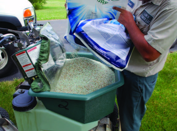
When calibrating the spreader pattern, make sure to use the same fertilizer or pesticide you plan to apply.
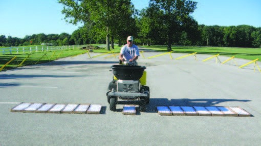
Step 4
Fill the hopper at least halfway with fertilizer to run the test. Pass over the boxes several times (moving in the same direction with each pass) until there is plenty of fertilizer in the front of the boxes. Remember, it is essential to go over the boxes from the same direction each time. Your goal is to go over the boxes enough times to collect enough material to fill collection tubes. Specifically, you want to collect enough material in the center box to fill a collection tube at least halfway. This might take two to eight passes over the collection boxes, depending on the size of your boxes. When you pass over the boxes, operate the ride-on at the speed you intend to use over turf. Ride-on spreaders have an advantage over walk-behind spreaders in that the impeller speed is more independent of its operating speed. The impeller on a ride-on maintains a constant speed by being linked to the engine speed or, in the case of some units, linked to an adjustable spreader motor control.
When you calibrate, be sure to record the ride-on spreader’s speed, gear, and RPM. For some units, you may be able to record the impeller speed. It is important to set and record the engine speed and any other impeller speed control during the calibration process so you can maintain it consistently later when you make applications.

Some units may have a hydraulic impeller motor that can adjust the spread width. When you calibrate one of these units, note the setting you are using. If you adjust this setting you will need to recalibrate.
Step 5
Measure what you collected in the boxes. Before you begin, leave each box in place - this is important because you will need to measure the distance between these boxes later. Arrange a series of collection tubes in a rack. You should have a tube for each box. Arrange the tubes in the rack. It is a good idea to number the tubes and boxes such as L1 and L2, etc., center, and R1 and R2, etc., to help keep them in order. Face the tubes in the same direction as if you were passing over the collection boxes.
Pour the contents of each collection box into its own corresponding tube (starting from one end). For this to work, all of the tubes must be identical. Tall and narrow containers are better because they will allow you to easily see the fertilizer distribution from one end of the spreader to the other. When you are done pouring all the boxes into the tubes, you will visually see the spreader’s distribution pattern. When you finish pouring the contents of one box into a tube, put it back on the ground where it was during the calibration run. As mentioned above, you will need to measure the distance between these boxes later.
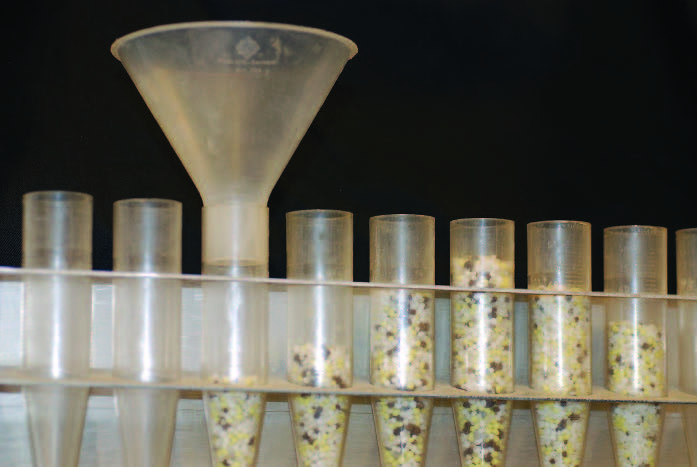
After your calibration run, pour the contents of each box into its own small container. Keep the boxes (and tubes) in order from left to right.
As the illustration shows, collecting fertilizer like this allows you to see if you are getting even distribution across the spread width or if one side is getting more than the other. The illustration also shows good and bad spreader patterns. It’s worth noting that it might take several attempts to get an ideal or desired pattern and that the pattern you achieve might not look as perfect as an ideal one.


This is a good spreader distribution pattern. Although not perfect, this might be as close as you can get to an ideal pattern. Make sure that the fertilizer distribution is evenly balanced on the left and right sides of the center. The arrow marks the center collection tube and direction of travel.
Step 6
If necessary, adjust the spreader pattern adjustment setting (not the gate opening), and then repeat Steps 4 and 5 (Pages 37-39). You can adjust the pattern in a number of ways depending on the make and model of the spreader. You can:
1. Change the opening size of the third hole adjustment
2. Adjust the sliding gate
3. Rotate the conical distribution device
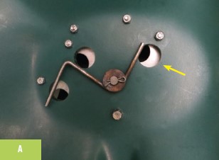


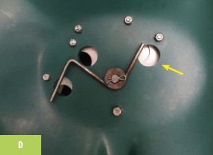
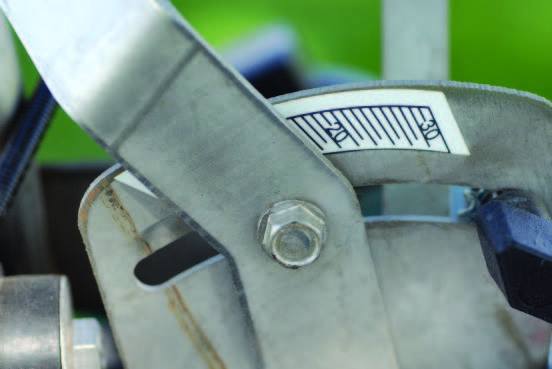
Some spreaders use the third hole to adjust the spreader pattern (A). Whether the third hole is open (A), closed (D), or somewhere in between (B-C) affects how the product is distributed onto the moving impeller.
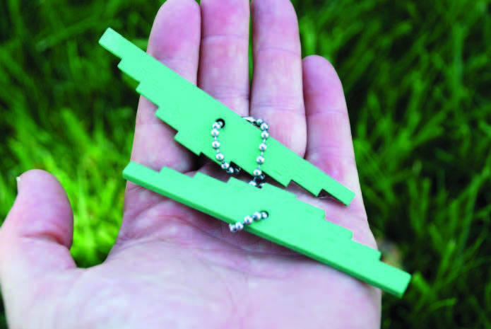
A third hole-type spreader should come with a calibration gauge. This gauge has stepped increments of 1/32 inch to allow the applicator to accurately measure the size of the opening. Use the gauge (not the numbers on the operating lever) to accurately document the opening size. After you obtain the desired spread pattern, document the step number and the product information for future reference.

Some spreaders use sliding gates to adjust their spread patterns. Be cautious because small adjustments in the gate can result in major product distribution changes.
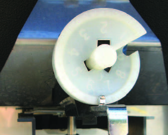
This spreader uses a rotating conical distribution device to adjust where the fertilizer hits the impeller, which adjusts the spread pattern.
COMPONENT TWO: DETERMINE THE EFFECTIVE SPREAD WIDTH
After you collect the product from your spreader, the tubes clearly show where the fertilizer is being applied. Once you adjust the spreader to achieve the desired pattern (equal amounts of fertilizer to the right and left sides of the spreader), find the tubes on the right and left that contain about half the product as the center tube. Go to the collection box on the left that corresponds to the tube that collected half the product. Measure the distance between this left box and the corresponding box on the right (through the center). This measurement is the effective spread width.
The effective spread width is the distance between spreader passes necessary for uniform distribution. In the example shown in the photos, the spreader’s effective spread width was 11 feet. To spread product uniformly, the operator of that spreader needs to make applications 11 feet apart. That is, the center of the wheel tracks should be 11 feet apart on each pass to make a uniform application. Experienced applicators will be able to approximate this distance through practice. New applicators can practice by using flags to mark the desired width.

The effective spread width for this spreader is the distance from the box that corresponds to the L4 tube to the box that corresponds to the R4 tube.
Start from the box on the left that collected half as much material as the center box. Measure the distance between that box on the left, through the center, to the corresponding box on the right (R4 to L4). This measurement is the effective spread width.
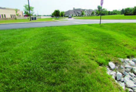
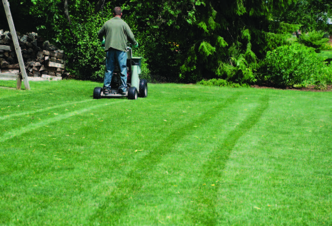
Notice the yellow-green and dark-green bands or stripes on this property. The bands were caused by overestimating the effective spread width or from an improper fertilizer pattern distribution adjustment.
Of course, the effective spread width will change from product to product. Some applicators overlap fertilizer applications by throwing fertilizer back to the center of the previous wheel tracks. Although this strategy works for most applications, it can slightly overestimate or underestimate the effective spread width. When you overestimate the effective spread width, some areas between the wheel tracks could receive too light of an application, which will cause a banding or striping effect. It is best to determine the effective spread width (using the method described here) than it is to rely solely on the wheel-to-wheel application strategy.
Some applicators overlap fertilizer applications by throwing fertilizer back to the center of the previous wheel tracks. Although this works for most applications, it can slightly overestimate or underestimate the effective spread width.
COMPONENT THREE: CALCULATE THE APPLICATION RATE
Before you can calculate the fertilizer application rate, you must first know the effective spread width (Component Two). The seven steps for calculating the fertilizer application rate appear below.
Step 1
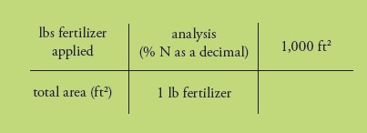
Determine how much fertilizer you want to apply per 1,000 square feet. Fertility rates for turf are based on the pounds of nitrogen (N) applied per 1,000 square feet. First determine how much actual N you need to apply per 1,000 square feet. This is your rate. Then, determine how much product you should apply per 1,000 square feet to deliver the planned rate. To do this, divide your N rate per 1,000 square feet by the percentage of N in the fertilizer bag. For example, let’s say you want to apply 1.0 pound of actual N per 1,000 square feet. Your fertilizer contains 20 percent N per pound. Remember: the first number in the analysis is the percentage of N per pound, so a 20-0-0 bag contains 20 percent N per pound. Divide the desired N rate by the percentage of N the product contains to get the amount of fertilizer:
1 lb ÷ 0.20 = 5 lbs of fertilizer
This is the amount of the fertilizer product you must apply to get the desired N rate. Put another way: 5 pounds of product (20-0-0) will give you 1 pound of actual N. This is the general formula to use to see how much fertilizer you need to apply:
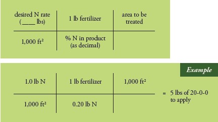
Another way of looking at a fertilizer with an analysis of 20-0-0 is to use the equation below. You need to apply 1.0 pound of actual N per 1,000 square feet. How much of the product will you need for a 1,000 square feet lawn? See the second green shaded box below. To get the answer, multiply the numbers in the top row straight across, do the same with the bottom numbers, and then divide the top number by the bottom number.
Step 2
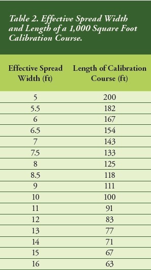
Set the length of the calibration course. In this example, you want the calibration course to measure 1,000 square feet (make the run over turf so you do not have to sweep up the fertilizer). The width of the calibration course is the effective spread width that you calculated in Component Two (Page 42). Determine the length by dividing 1,000 square feet by the effective spread width. For example, let’s say your spreader has an effective spread width of 11 feet: 1,000 ft2 ÷ 11 ft = 91 ft
This means your calibration course is 11 feet wide by 91 feet long. Place flags at the start and finish of the calibration course. Table 2 provides calibration course lengths based on various effective spread widths.
Step 3
Set the gate opening. Set the opening based on the fertilizer bag, ride-on manufacturer recommendations, input from peers, or input from fertilizer distributors. Consider this setting as a starting point for your rate calibration.
Step 4
Pour an entire fertilizer bag into the hopper. You will know exactly how many pounds of product this is by looking at the net weight written on the bag. Alternatively, weigh out a smaller amount to reduce the amount of fertilizer you need to add to the hopper. You could use a weight such as 25 pounds.
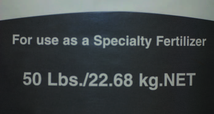
A fertilizer bag always indicates the weight it contains. Bags are typically 40 or 50 pounds.
Step 5
Apply the product over the calibration course. Use a shop vacuum or similar device to collect all the remaining fertilizer from the hopper. Pour the contents from the shop vacuum into a bucket and weigh it. Subtract the empty weight of the bucket, and that’s how much fertilizer was left in the hopper after your calibration run. Subtract this weight from the total weight you put in the hopper in Step 4. This will tell you how many pounds of fertilizer you applied over the calibration course. For example, let’s say you added 25 pounds of fertilizer to the hopper in Step 4. After the calibration run, you collected 20 pounds from the hopper. This means you applied 5 pounds of fertilizer to 1,000 square feet. Always repeat this process a second time to verify your results.
Clean Your Vacuum
If you are calibrating a combination product that contains both a fertilizer and a pesticide, you must clean out the shop vacuum afterward to remove all residues. Follow label restrictions when it comes to PPE and all instructions from the shop vacuum manufacturer on how to properly clean the vacuum.

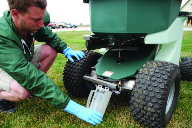
A shop vacuum will help you remove the fertilizer that was left in the hopper. Subtract what’s left from the amount you started with to calculate how much fertilizer you applied to the calibration course.
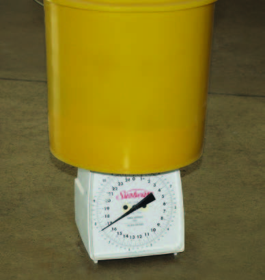
Use a scale like this one or a bathroom scale to weigh the product left in the hopper after the calibration run.
Step 6
Adjust the spreader if necessary. You should make adjustments if the amount that you applied over the calibration course differs more than 10 percent from the amount of fertilizer you want to apply. Make the necessary gate opening adjustments and repeat Steps 4 to 5 until you achieve the desired application rate.
Warning: do not go over the same calibration course more than once. Each time you calibrate, move your course over a distance that is at least equal to the effective spread width so that you don’t over apply fertilizer to your turf calibration area.
Step 7
Record the speed and/or gear, engine RPM, impeller speed setting (if applicable), and gate opening. It is also important to write the brand of fertilizer and other information that will identify that product — including its SGN. Keep this information for future reference. It is important to remember that the formulation of a specific brand may change over time, which can throw off your calibration. Two other ways to collect this information are to save the actual bag and/or to place a little fertilizer in a container for reference. If you use another fertilizer product, you will have to repeat the calibration process.

A wide variety of turf fertilizers are available to turf professionals. Turf fertilizers vary in size and shape, which affects their distribution with a spreader.

CHECK THE ACCURACY OF YOUR CALIBRATION
After you calibrate the spreader, double-check its accuracy. Here is the general formula to determine how much actual N you applied:
To get the answer, multiply the numbers in the top row straight across, do the same with the bottom numbers, and then divide the top number by the bottom number. Let’s say your goal was to apply 0.5 pound of N per 1,000 square feet to a lawn that is 7,000 square feet. The product you calibrated for was a 12-0-5 fertilizer and came in a 50-pound bag. You filled the hopper with all 50 pounds of the product and spread the fertilizer until the hopper ran dry just as you finished treating the lawn.
How close to the 0.5 pound of N per 1000 square feet did you apply?

In this example, the actual amount of fertilizer applied was 0.86 pound per 1,000 square feet. This is an overapplication because the goal was 0.5 pound of N per 1,000 square feet. It doesn’t seem like much, but the turf received 72 percent more than the target rate of fertilizer. In other words, your fertilizer bag is covering much less than it should have and nearly doubled your fertilizer cost.

Making the Trim Pass
Make the trim pass along the border of the lawn before fertilizing the entire turf. This first pass allows you to observe the entire property and note any obstacles. The trim pass also lets you refresh your memory of the lot’s size and shape. Another advantage of the trim pass is that you reduce the amount of fertilizer on impervious surfaces such as driveways, roads, and sidewalks, so you do not apply the product off-target. Even with a trim pass some product may go onto hard surfaces. Sweep or blow this small amount of product off hard surfaces back onto the lawn. The mechanics of a trim pass will vary with the specific brand of ride-on spreader. With some makes (like PermaGreen®) you close the third hole and deploy the edge guard during a trim pass. After the trim pass, open the third hole back to the position (using the stop) that you determined through the pattern calibration. With a Z-Spray® spreader, there is no third hole. So to reduce the rate by half, adjust the rate setting by half — determined from a second calibration to achieve half the rate — and deploy the edge guard during the trim pass. It is important to note that you can’t just turn the rate dial down by half. You need to calibrate to get the proper dial setting for the half rate.
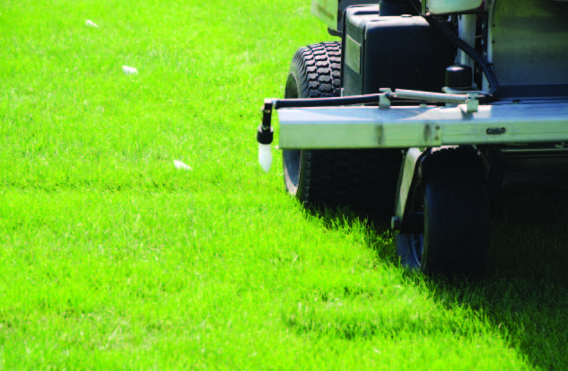
The edge guard (deflector) is a physical barrier that prevents the fertilizer from going onto impervious surfaces. Without a guard, the spreader shown below would apply fertilizer onto the paved surface. Always blow or sweep fertilizer off any sidewalks back into the turf.
Using the Sprayer and Spreader at the Same Time
Remember that you must independently calibrate the sprayer and spreader units on a ride-on. Ride-ons are built to deliver liquids and solids through two separate and independent processes. The fertilizer spreader has an impeller that throws out granules, the liquid is delivered either through a single-nozzle (boomless) or a multi-nozzle boom.
The question is: can you operate the spreader and sprayer at the same time since they are independently calibrated? In other words, can you apply fertilizer (spreader) and herbicide (sprayer) at the same time?
While many applicators do this, be aware that there may be limitations to doing both at once — and these vary by sprayer type.

This applicator is applying fertilizer and herbicide at the same time.
SINGLE-NOZZLE BOOMLESS SPRAYER
Before you decide to use the sprayer and spreader at the same time on a single-nozzle boomless sprayer, consider the equipment. Compare the nozzle’s effective spray width to the spreader’s effective spread width. Most likely, those widths will not be the same. Spreaders typically spread the fertilizer wider than sprays.
When determining how to space their combination passes, applicators typically use the effective width of the spreader, which can be a foot or more wider than the effective sprayer width. While the fertilizer will be put down uniformly at the right rate, there could be areas that do not receive the proper dose of herbicide. These underdosed areas can pose problems, especially when you are treating weeds like crabgrass, white clover, and dandelions that uniformly occur across an area. Some applicators report that they notice these weedy, underdosed strips from time to time, while others comment that they don’t. So, should this concern you?
It should if you consider callbacks. Lawn care companies that want to avoid callbacks choose not to make important applications (like the first preemergence crabgrass control application) by simultaneously spraying an herbicide and spreading a fertilizer. Instead, they might choose to spread a combination product (like one that contains both a preemergence herbicide and a fertilizer) and not use the sprayer for this first application. Or, they might use the lawn gun to make a liquid preemergence herbicide application. To get the most accurate and consistent results with a single-nozzle boomless ride-on, do not operate the sprayer and spreader simultaneously unless the spray width and spread width closely match. Many applicators spray and spread at the same time only when they are spot spraying weeds, not when making spray applications to the whole lawn. However, despite the inconsistency that can occur from spreading and spraying at the same time, many applicators accept the increased risk of a few skipped weeds in order to increase the efficiency of their operations.
MULTI-NOZZLE BOOM SPRAYER
Boom-style ride-on units have the same uniformity issue as boomless equipment, although a wider boom may make the effective spray width closer to the effective spread width. The question is whether the effective widths (spray and spread) are close enough to achieve a uniform application. On some models, an impeller speed control can alter the spread width to more closely match the sprayed width. However, you must calibrate these units so that the effective spread width matches the effective spray width. That complicates the calibration process. If you are going to spread and spray at the same time, make sure the effective spread width and spray width are similar. In any case, uniform applications are only possible when the effective spread width and the effective spray width are similar. While it may be possible to set the effective spray width and effective spread width to be the same, it will be more difficult to calibrate and operate accurately, depending on the products and equipment setup. Applicators are the only ones who can evaluate their work over time (during return visits) to see whether running the spreader and sprayer at the same time results in high quality turf that has few weeds.
Keep the Owner’s Manual
Each ride-on sprayer/spreader comes with an operating manual that provides useful suggestions for operating the equipment effectively and safely. Familiarize yourself with this information. The manual also includes important contact information if you need to ask the manufacturer questions. In many cases, the operator’s manual provides useful photos, illustrations, and step-by-step procedures to help keep the unit operating. The manual will tell you what parts need daily inspection, what parts need to be greased (and at what intervals), and the number of working hours between oil and filter changes. It also is a handy resource for information about the exact identification number if you need to order parts. It is a good idea to keep written records of the service and maintenance performed on each ride-on unit. In some cases, manufacturers require proof that you followed certain maintenance schedules before they will pay for any parts and labor that may be covered under their warranties. Keeping track of all your maintenance also can add significantly to the resale value of your used equipment. Also, don’t forget to promptly fill out and return the warranty and registration cards that come with the unit. This will not only help ensure your equipment is properly warrantied, it also will allow the manufacturer to contact you with important information about your equipment such as recalls, upgrades, or add-ons.
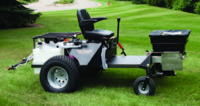
There are many ride-on sprayer/ spreaders available. Most can be calibrated using the methods described in this publication.
Conclusion
Turf management is a science that requires you to understand agronomic principles, pest biology, fertilizers and pesticides, and application equipment. Ultimately, you need to apply any products uniformly and at the correct rate. Calibrating your equipment is part of your overall responsibilities as turf manager. Calibration ensures that you apply products correctly the first time, which can save you time and money, and lead to turf you can be proud of. Turf provides a safe place for recreation and provides a pleasant setting for people to enjoy the outdoors. With proper calibration, you can maintain a high-quality athletic field, residential yard, commercial property, or cemetery that all can enjoy.

Find Out More
The Purdue Turf Science Program and Purdue Pesticide Programs offer a number of publications on related topics to help you manage your operations better. All publications are available from The Purdue Extension Education Store: the education store | (888) EXT-INFO (396-4636)

Calibrating the Hose Reel Lawn Care Sprayer (PPP-85). Avoid callbacks by applying the right amount of product with your hose reel sprayer.

The Impact of Water Quality on Pesticide Performance (PPP-86). Learn how water quality can affect your applications and bottom line.

Measuring Pesticides: Overlooked Steps To Getting the Correct Rate (PPP-96). Find solutions to common measuring problems.

Turfgrass Weed Control for Professionals (AY-336). Develop effective weed control programs for golf courses, athletic fields, sod farms, residential and commercial lawns, and other turf systems.
Find Purdue Extension publications, research reports, and educational opportunities
on the Purdue Turfgrass Science website: www.agry.purdue.edu/turf.
Acknowledgments
A special thanks to the Midwest Regional Turf Foundation and Indiana Professional Lawn & Landscape Association for partial funding of this publication. The authors would like to thank the following for their comments that improved the accuracy and readability of this publication.
Bob Andrews, The Greenskeeper
Bob Avenius, TruGreen
John Boyd, University of Arkansas
Jamie Breuninger, Dow AgroSciences
Jim Brosnan, University of Tennessee
Bob Bruss, NuFarm Americas
Wayne Buhler, North Carolina State University
Larry Caplan, Purdue University
Jim Colias, Matt’s Lawncare & Landscaping
Chad Frank, Synergistic Solutions
Dave Gardner, The Ohio State University
Matt Giese, Syngenta
Jim Grubb, Grubbworm Landscaping
Tad Grubbs, C&S Turf Care Equipment
Ben Hamza, TruGreen
Mike Hornbach, Purdue University
Tom Jessen, PermaGreen
Ray Lacobuccii, TruGreen
David McGaugh, AG Seminars
Richard Parish, Consulting Engineer
Zac Reicher, University of Nebraska
Judd Scott, Vine & Branch
Bobby Walls, FMC
Disclaimer
This publication is intended for educational purposes only. The authors’ views have not been approved by any government agency or business. The publication is distributed with the understanding that the authors are not rendering legal or other professional advice to the reader, and that the information contained herein should not be regarded or relied upon as a substitute for professional consultation. The use of information contained herein constitutes an agreement to hold the authors harmless for liability, damage, or expense incurred as a result of reference to or reliance upon the information provided. Reference in this publication to any specific commercial product, process, or service, or the use of any trade, firm, or corporation name is for general informational purposes only and does not constitute an endorsement, recommendation, or certification of any kind by Purdue University. Individuals using such products assume responsibility for their use in accordance with current directions of the manufacturer.

June 2013/REV 2020
![]()
Order or download materials from Purdue Extension • The Education Store