

Agricultural Spray Nozzles
A COMPREHENSIVE REVIEW
Fred Whitford, Director, Purdue Pesticide Programs
Rajeev Sinha, Applications Engineer, Corteva Agriscience
Debora de Oliveira Latorre, Application Training Lead and Industry Liaison, TeeJet Technologies
Bryan Young, Professor of Weed Science, Purdue University
Erdal Ozkan, Professor and Pesticide Application Technology Specialist, The Ohio State University
Stephen Pearson, Business Development Manager (retired), TeeJet Technologies
John Obermeyer, Integrated Pest Management Specialist, Purdue University
Kevin Leigh Smith, Continuing Lecturer and Communication Specialist, Purdue Agricultural Sciences Education and Communication
Contents
Introduction to Hydraulic Spray Nozzles.. . . . . . . . . . . . . . 4
The Evolution of Nozzle Technology.. . . . . . . . . . . . . . . . . . . . . 8
Commercial Application Services Emerge.. . . . . . . . . . . . . . . . . . 9
New Pesticide Products Commercialized.. . . . . . . . . . . . . . . . . . 10
Silent Spring Places Crosshairs on Pesticides.. . . . . . . . . . . . 10
Spraying Systems Develops Droplet Size Analyzer.. . . . . . 10
Universities Focus on Pesticide Education.. . . . . . . . . . . . . . . . . 11
Reduced Tillage More Widely Accepted.. . . . . . . . . . . . . . . . . . . . 11
Automated Rate Controllers Drive Changes.. . . . . . . . . . . . . . . 12
Genetically Modified Crops Become a Game Changer.. . . . 13
Soybean Rust Shifts Focus to Thorough Spray
Coverage.. . . . . . . . . . . . . . . . . . . . . . . . . . . . . . . . . . . . . . . . . . . . . . . . . . . . . . . 14
EPA Requires Spray Droplet Information on Labels.. . . . . . 16
Looking Toward the Future.. . . . . . . . . . . . . . . . . . . . . . . . . . . . . . . . . . . . 16
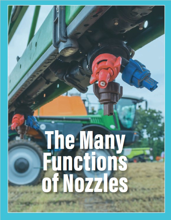
The Many Functions of Nozzles.. . . . . . . . . . . . . . . . . . . . . . . . . . . 18
Turn Liquid Streams into Droplet Clouds.. . . . . . . . . . . . . . . . . . . 20
Create Droplets Within a Specific Size and Density. . . . . . 21
Form a Specific Spray Angle Width.. . . . . . . . . . . . . . . . . . . . . . . . . . 22
Create the Spray Pattern.. . . . . . . . . . . . . . . . . . . . . . . . . . . . . . . . . . . . . . . 22
Meter the Flow of the Liquid.. . . . . . . . . . . . . . . . . . . . . . . . . . . . . . . . . . 23
Control the Droplet Velocity.. . . . . . . . . . . . . . . . . . . . . . . . . . . . . . . . . . . 23
The Push to Make Nozzles More Precise. . . . . . . . . . . . . 24
Advances in Analytical Equipment Measuring
Droplet Sizes.. . . . . . . . . . . . . . . . . . . . . . . . . . . . . . . . . . . . . . . . . . . . . . . . . 25
Acceptance of International Testing Standards. . . . . . . . . . . 28
Transition to Thermoplastic Materials. . . . . . . . . . . . . . . . . . . . . . . 29
Use of Injection Molding.. . . . . . . . . . . . . . . . . . . . . . . . . . . . . . . . . . . . . . . 29
Utilization of 3D Printers.. . . . . . . . . . . . . . . . . . . . . . . . . . . . . . . . . . . . . . 30
Characterizing Droplet Size and Spray Pattern. . . . 32
Droplet Size and Distribution. . . . . . . . . . . . . . . . . . . . . . . . . . . . . . . . . . 33
Flow Rate.. . . . . . . . . . . . . . . . . . . . . . . . . . . . . . . . . . . . . . . . . . . . . . . . . . . . . . . . . . 42
Spray Angle.. . . . . . . . . . . . . . . . . . . . . . . . . . . . . . . . . . . . . . . . . . . . . . . . . . . . . . . 43
Lateral Distribution.. . . . . . . . . . . . . . . . . . . . . . . . . . . . . . . . . . . . . . . . . . . . . . 44
Environmental Impacts. . . . . . . . . . . . . . . . . . . . . . . . . . . . . . . . . . . . . . . . . 45
Construction Materials and Adaptive Designs. . . . 46
External Dimensions.. . . . . . . . . . . . . . . . . . . . . . . . . . . . . . . . . . . . . . . . . . . . 48
Entrance Orifice Meters Liquid into Nozzle.. . . . . . . . . . . . . . . . 48
Structural Modifications Within a Hydraulic Nozzle.. . . . . 49
Structural Modifications to the External Exit Orifice.. . . . . 52
Materials Used in Nozzle Tips and Bodies.. . . . . . . . . . . . . . . . . 52
Nozzle Types in the Marketplace. . . . . . . . . . . . . . . . . . . . . . 56
Nozzles That Primarily Fit on Spray Booms.. . . . . . . . . . . . . . . . 57
Other Hydraulic Nozzles. . . . . . . . . . . . . . . . . . . . . . . . . . . . . . . . . . . . . . . . 62
Nozzle Tip Screens, Caps, and Turrets.. . . . . . . . . . . . . . . . 66
Screens Help Prevent Nozzle Plugging.. . . . . . . . . . . . . . . . . . . . . 67
Spray Boom, Turrets, and Caps.. . . . . . . . . . . . . . . . . . . . . . . . . . . . . . . 71
Demystifying the Nozzle Selection Process. . . . . 74
Altering One Variable Changes All Others.. . . . . . . . . . . . . . . . . . 76
Criteria for Selecting New Nozzles. . . . . . . . . . . . . . . . . . . . . . . . . . . 78
Working Through a Nozzle Chart.. . . . . . . . . . . . . . . . . . . . . . . . . . . . . 84
What Happens If Nozzle Spacing Differs from Catalog?.. . 86
Criteria for Selecting Fertilizer Nozzles.. . . . . . . . . . . . . . . . . . . . . 88
Maintenance and Replacement.. . . . . . . . . . . . . . . . . . . . . . . 90
Cleaning Screens and Nozzles. . . . . . . . . . . . . . . . . . . . . . . . . . . . . . . . 91
Checking Nozzles for Wear.. . . . . . . . . . . . . . . . . . . . . . . . . . . . . . . . . . . . 92
The Unsung Heroes of Liquid Applications.. . . . 100
Acknowledgements. . . . . . . . . . . . . . . . . . . . . . . . . . . . . . . . . . . . . . . . . 103
Disclaimer.. . . . . . . . . . . . . . . . . . . . . . . . . . . . . . . . . . . . . . . . . . . . . . . . . . . . . . . 103
Introduction to Hydraulic Spray Nozzles
Economists predict that the cost of pesticide application equipment will continue to rise as technological advances related to precision application become commercially available. These breakthroughs primarily include machine learning, robotic automation, pulse-width modulation, and remote and proximal sensing capabilities. Familiar technologies such as direct inline injection, computer vision guided, global positioning systems, and data logging continue to improve. And technologies such as remotely piloted aerial application systems that seemed futuristic only a few years ago are being rapidly adopted for pesticide applications.
These rapid advances and their general adoption are expected to:
• Increase application and operational efficiency
• Permit timely and weather-appropriate applications
• Boost pesticide efficacy by improving application quality
• Save input and troubleshooting costs
• Provide environmental protections by applying product more precisely
• Improve applicator safety through equipment design
• Reduce spray loss
• Reduce application failures and required resprays
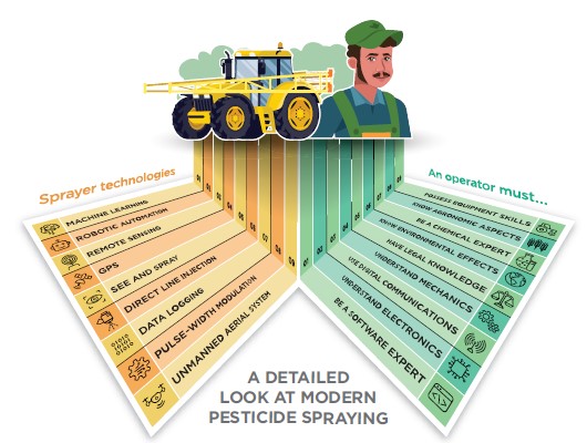
As sprayer technology evolves and advances, the need for highly trained operators has grown. Just a few years ago, if you could drive a truck, you could drive a sprayer. Back then, it was pretty much putting the equipment in gear (remember manual transmissions) and being able to drive straight. An employee could drive a sprayer in the spring through fall, and then deliver fuel and propane in the winter.
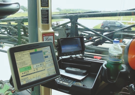
Old sprayer technology has given way to modern onboard technologies that facilitate more precise applications. Today’s sprayers are computers on wheels.
Today’s sprayer operators must be well versed in onboard software, electronics, digital communication, and mechanics. Operators also should have a working understanding of the legal, environmental, chemical, and agronomic aspects of their job. There is no comparison between today’s sprayer operators with yesterday’s applicators.
Application equipment may be computer-driven, but nothing happens without nozzles.
As we explore and implement these new technologies, it is important not to overlook advances in hydraulic nozzle technology and to acknowledge the critical role they play in the application process. In general, a nozzle is undoubtedly one of the more important pieces of spraying equipment that influences (among other things) the quantity, uniformity, droplet size, and potential for off-target movement of pesticides. Trade magazines are filled with stories about technologies and practices that add precision to applications, but stories about new advances in nozzle materials, design, and functionality are rare. Nozzles are often relegated as “old” technology.
Some might think, “It’s just a nozzle; how important can it be? I have used the same nozzle all my life and it works.” Such remarks clearly demonstrate how many people underestimate the humble nozzle. Many wrongly assume that nozzle designs are mere variations on one another, and that they are more alike than not. As a result, operators tend to stretch a nozzle’s utility, assuming a single design is appropriate for all applications. Many operators are guilty of exchanging worn sets of nozzles for new sets of the same nozzle without considering what they actually need for the job at hand.
The simple fact is that even the most advanced sprayers can be undermined by nozzles that are worn, damaged, or operated in ways that go against their intended use. Whether it is a pull-behind sprayer, a turf tank-hose sprayer, or an agricultural sprayer, achieving optimum performance (or getting your money’s worth out of equipment and product) with these newer technologies may be compromised by having the wrong set of spray nozzles.
Nozzles are one of the most economical components in an application, which may be why many overlook their importance. Ultimately, what we are saying is that a set of 72 nozzles on a 120-foot boom may cost hundreds of dollars applying thousands of dollars of agrichemical products over the course of their lifetime. The same could be said for the importance of nozzles in an $85,000 right-of-way truck sprayer, a $20,000 ride-on turf sprayer, or a $300 backpack sprayer.
Nozzles are generally “hidden” from view when it comes to their importance in spray applications.
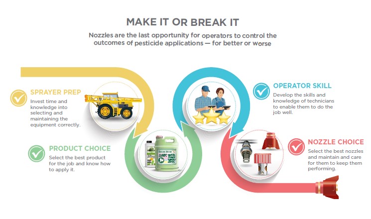
It’s wrong to assume that a nozzle’s importance is commensurate with its relative cost. Nozzles are the working end of application equipment that moves the diluted product out of the sprayer and onto the target. Choosing the right nozzle for the job is the last opportunity operators have to control pesticide application outcomes. Application equipment and products have evolved and so have nozzles. Many new nozzle designs occurred during the last two decades. Today’s spray nozzles are not what your grandfather used decades ago. Modern nozzles are designed and manufactured to reflect the needs and expectations of customers, industry, and regulatory agencies.
In many ways, the science behind the designs, materials, and capabilities of today’s nozzles is as impressive and complicated as the chemistries being applied. This publication will discuss the current state of spray nozzle technology as it relates to today’s pesticide applications. By better understanding the science, we hope this will enhance the selection process and optimal use to save applicators money and make the most effective applications possible.
The Evolution of Nozzle Technology

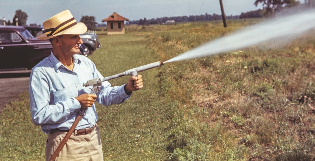
Handheld, high-pressure pesticide applications (1940s).
Think about the hundreds of thousands of aerial, ground, orchard, and backpack sprayer applications that are made around the world each year. Now consider that each combination of equipment, crop, and pesticide may warrant a specific nozzle design. You begin to appreciate why we have such a wide variety of nozzles to choose from. But this wasn’t always the case. Manufacturers’ catalogs during the early era of pesticides offered a limited nozzle selection, because the chemicals and application methods had yet to be developed to the extent that they are now. In the 1940s, the introduction of 2,4-dichlorophenoxyacetic acid (2,4-D) revolutionized weed control in agriculture. Suddenly, foliar sprays became a viable and economic alternative to pulling a cultivator across the field. However, 2,4-D came to market without much consideration for how it would be applied.
As a result, many of the First 2,4-D applications were via 55-gallon drums and modified industrial nozzles. Beyond the need 2,4-D created, other events helped shape and advance nozzle design.
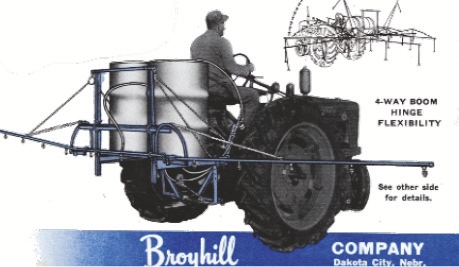
In the 1940s, Spraying Systems partnered with Broyhill to launch the original line of TeeJet® agricultural spray tips for applying 2,4-D.
Commercial Application Services Emerge
Businesses that offered commercial pesticide applications experienced increased demand to control pests in many situations. Landscape commercial applicators required high-volume and boomless nozzles to reach high into foliage unlike those used in agricultural row crops. Nozzle manufacturers responded by investing in nozzle research and building facilities to manufacture them.
New Pesticide Products Commercialized
The pesticide manufacturing sector expanded after the introduction of 2,4-D and the insecticide dichlorodiphenyltrichloroethane (DDT) in 1945. Over the next few decades, pesticide scientists discovered additional herbicides, insecticides, and fungicides to tackle pests found beyond agricultural production - in and around homes and industrial sites, and for livestock. While new pesticide chemistry was effective on the targeted pests, nozzles played a critical role in getting the product to where it was needed. It soon became apparent that pesticide manufacturers would need to consult with nozzle manufacturers to ensure that they each understood the needs of the other.

Silent Spring Places Crosshairs on Pesticides

Marine biologist Rachel Carson raised serious questions about pesticide use in her 1962 book Silent Spring. The book awakened the public and federal government that action was necessary to preserve and protect wildlife against the negative impacts of pesticides. Silent Spring put the pesticide community on notice.
Carson’s book became the impetus for transferring pesticide registration and enforcement authority from the United States Department of Agriculture (USDA) to the newly created United States Environmental Protection Agency (EPA) in 1970. The EPA began to focus on product evaluations based on scientific data collected under federally mandated testing guidelines.
This helped strengthen product labels, mainly in applicator safety, environmental stewardship, and container disposal. However, the EPA still largely leaves it to pesticide manufacturers to provide application recommendations on their product labels.
Spraying Systems Develops Droplet Size Analyzer
Pesticide development brought new products, including translocated and growth regulator herbicides, and systemic fungicides/insecticides. Field research showed that carrier volume (such as, gallons per acre) and droplet size influenced the efficacy and distribution of these products. With these findings, pesticide manufacturers focused on nozzle design to meet specific needs.
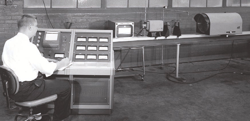
One of the first attempts to classify droplet size was around 1968. In this photo Robert Williams, engineer, is running a test through the first droplet size analyzer at Spraying Systems at their Illinois headquarters.
In general, spray nozzles were required to accomplish two primary functions. First, they must consistently deliver a specific volume uniformly across an area. Second, they must generate a specific droplet size spectrum. However, quantifying droplet size was (and arguably still is) challenging. Spraying Systems developed its first electronic droplet size analyzer in 1968. The analyzer assigned diameters to the droplets that nozzles produced, allowing manufacturers to classify their nozzles and begin to address key questions posed to them by those working in pesticide application technology.
Universities Focus on Pesticide Education
The EPA has long required pesticide applicators to become certified by meeting minimum competency standards. It was left to state cooperative extension services and state agricultural colleges to offer certification training and, in some states, continuing education to pesticide applicators.

It is no surprise that people preferred a one-size- fits-all nozzle, and state extension educators heard (and still hear) this a lot. However, just as pesticide companies saw nozzle-specific improvements for certain applications, researchers at universities independently confirmed that applying the right pesticide with the wrong nozzle seldom gave the expected results.
Researchers today still practice the same techniques to evaluate nozzles that were developed nearly 50 years ago. These techniques include using paper targets and spraying a fluorescent tracer over that to determine spray coverage (a qualitative approach). When determining spray quantity, researchers use other types of durable targets made from plastic, or metal, or petri dishes
Reduced Tillage More Widely Accepted
The 1970s would usher in a major shift in agricultural soil conservation practices. Weed control, which had largely been accomplished using tillage, was making its way toward minimum tillage strategies. By limiting how much tillage disturbs the soil, researchers learned they could better protect soil against erosion caused by rainfall and wind. As more growers adopted reduced tillage practices, they had to adapt to changes in weed species and application timings. There also was the challenge of reaching the target pest through crop residue. Pesticide applications shifted in their timing. What once was applied during tillage in the early spring shifted to soil-applied residual chemistries followed by a foliar application after crop emergence.
Automated Rate Controllers Drive Changes
The introduction of automated rate controllers in the 1980s required nozzles to maintain consistent flow rates and patterns. The controller would adapt to varying travel speeds by modulating the spray pressure (PSI). With these controllers, operators set the desired application rate (in gallons per acre), which causes the nozzle to generate flow at a given pressure. Before these controllers, the application rate could over- or underdose when the sprayer sped up or slowed down in the field (during turns, obstacles, or topography). Rate controllers were developed to monitor travel speed and compensate for any speed changes using pressure. If a sprayer slowed down, a regulating valve would alter the flow to reduce the spray pressure at the spray tip. If the equipment went faster, the rate controller would increase the pressure at the nozzle to increase the flow rate. Rate controllers allowed areas being sprayed to receive consistent doses at different speeds.
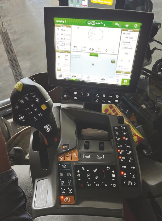
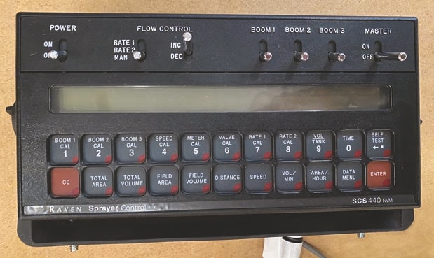
Most sprayers today are equipped with an automated rate controller integrated into the cab’s computer system (A), but it was a separate module “box” in the early days of its adaption (B).
Left unchecked, rate controllers might go to relatively extreme pressures to compensate for big changes in travel speed. If the pressure is too low for the nozzle, then the spray liquid isn’t correctly atomized — this results in larger droplets and, in extreme cases, the spray pattern can collapse and lead to gaps in spray coverage along the boom. If the pressure is too high, the droplets get too fine (droplet size and pressure are inversely related), which increases drift potential. The XR TeeJet® nozzle was developed to maintain a more uniform spray pattern across spray pressures that were lower and higher than the original recommendation of 40 PSI. It is important remember that although this type of nozzle can be operated under a wider pressure range, the nozzle won’t prevent a sprayer from producing driftable fine droplets at higher spray pressures. There are other nozzles with exit orifices that can change in size in response to pressure changes. This allows them to operate over a wider range of pressures.
Today, we have systems that will automatically shift between nozzles or run nozzle combinations in real time to maintain a steady spray pattern, flow, and droplet size. And, of course, there is pulse width modulation (PWM) that makes pressure-based rate controllers obsolete. Instead of using pressure to compensate for changes in travel speed, PWM technology uses an electronic solenoid to vary duty cycle (proportion of time the solenoid valve is open) to maintain the required flow. To prevent gaps, the alternate nozzle is on while its neighbor is off. PWM systems can hold the spray pressure constant to maintain a consistent droplet size spectrum. It should be noted that some nozzles work with PWM systems, and some do not. Many catalogs will list what nozzles are approved for PWM systems.
Genetically Modified Crops Become a Game Changer
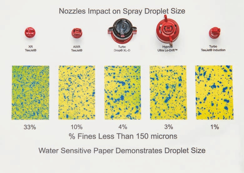
In the mid-1990s, the introduction of Roundup Ready® (glyphosate-resistant) soybeans launched broadcast, broad-spectrum weed control in a single application. However, the concern was that the wide adoption of Roundup would increase spray drift that would make off-target plants susceptible to damage. Monsanto began to reassess the need to move from conventional flat fan nozzles that produced a high proportion of droplets small enough to drift. A reference often used to define a driftable droplet is one that is less than 150 microns (μm) in diameter. A micron is 1/25,000 of an inch, or about the diameter of a human hair. However, there are other reference points that define driftable droplets. Monsanto and Spraying Systems worked to develop Turbo TeeJet® nozzles alongside Roundup Ultra® formulations. As tens of millions of acres converted to this new seed technology, nozzle manufacturers developed nozzles that produced fewer driftable fines. Thus, the nozzles were developed to prevent widespread glyphosate spray drift.

Monsanto promoted the use of these low-drift nozzle options when spraying Roundup over their patented, genetically modified soybeans. Sprayer operators readily adopted these new tips, encouraging nozzle manufacturers to develop a diverse variety of low-drift nozzles. The nearly universal acceptance of Roundup Ready® soybeans in the United States would begin a push by the manufacturers to introduce nozzles with turbulence chambers and air injection ports that lead to more nozzles creating larger spray droplets.
Soybean Rust Shifts Focus to thorough Spray Coverage
While herbicides became integral to field crop production, fungicides represented only a minor part of agronomic crop pesticide usage. However, fungicide and insecticide applications have (and are) fundamental in specialty crop production. Soybean rust, first detected in the United States in 2004, represented a new and significant economic threat to millions of soybean acres. Soybean rust first shows symptoms in the lower parts of the plant and works toward the top of the plant. So, by the time growers notice the problem in the mid- to upper canopy, it may be too late to spray any fungicide.

Most fungicides are not systemic like some herbicides are, so fungicides do not translocate in plant tissues after application. As a result, thorough preventative spray coverage on the foliage is critical for rust control. This complete coverage is even more challenging during later growth stages when the plant is close to having a full canopy. Penetrating droplets inside the canopy of fully-grown soybean plants is a much bigger challenge.
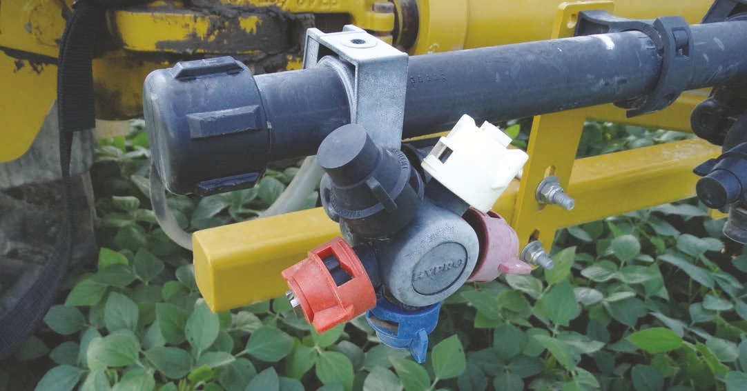
This air induction exit nozzle is an asymmetric nozzle. It has a forward spray at 30° and a 70° backward fan, which helps to increase the spray intercepted by the canopy.
This nozzle body can hold two nozzles oriented forward and backward relative to the sprayer’s direction of travel.
Using nozzles that produce a relatively high number of small droplets is one way to improve spray coverage. Another way to improve soybean canopy coverage is to use nozzles with twin spray patterns that penetrate the canopy from two different angles (forward and backward). Twin-pattern nozzles had been in the market many years before soybean rust became an issue; however, these conventional twin-pattern nozzles were ineffective because they produced a large number of driftable fine droplets. When the canopy is tall and dense, these droplets were unable to penetrate middle or lower parts of the canopy (needed for soybean rust control) or in the middle parts (needed to control diseases like white mold, which usually starts when flowering begins). In other words, nozzle manufacturers had to change the spray droplet spectrum of the conventional twin-flow nozzles for effective fungicide applications. This led to manufacturers designing twin-pattern spraying schemes. One scheme featured two exit orifices built into a single nozzle that had fewer of the drift-prone small droplets. Another scheme featured two nozzles built into a single cap that produced two different angles of deflections for the spray patterns.
EPA Requires Spray Droplet Information on Labels
In the 2010s, manufacturers reformulated auxin mimic herbicides with newly traited crops to combat glyphosate-resistant weeds. These new dicamba (2016 in Canada, 2017 in the United States) and 2,4-D (2018) pesticide formulations were designed to be less volatile than their previous incarnations, but they still had the potential to cause significant injury if they drifted onto sensitive crops or field crops that did not have auxin herbicide resistance traits. In response to concerns about auxin herbicide drift, state agencies worked with the EPA to place specific limitations and requirements on pesticide labels. Dicamba could only be applied using nozzles that produced droplets that were extremely coarse to ultra- coarse, and that produced a lower percentage of driftable fine droplets. 2,4-D could only be applied with nozzles that droplets ranging from coarse to extremely coarse. Manufacturers of these dicamba and 2,4-D formulations provide information (frequently on their websites) that lists the approved nozzles and their required spray pressure ranges, which makes it easier for applicators to select the correct nozzle.

Looking Toward the Future
Let’s make a few educated guesses about where agricultural spraying is going. If we could jump ahead in time, perhaps we would look back on this era in nozzle development as the precision application phase. Expensive chemistries, invasive pests, pesticide resistance, genetically modified crops, endangered species, larger operations, and increased public awareness of environmental stewardship created a need for more efficient and targeted spraying. In the future, pulse width modulation (PWM) on commercial sprayers will largely replace the older pressure-based method of rate control by cycling nozzles on and off to compensate for changes in ground speed rather than adjusting pressure. Other innovations (such as recirculating booms, overlap prevention, and turn compensation) have already been developed.
These innovations require new nozzle designs that can maintain excellent spray distribution in the direction of travel, rapid and complete spray pattern formation, excellent spray distribution across the boom, skip-free application, and droplet size consistency. This makes it possible to develop precision or targeted spraying. Looking ahead, targeted spraying systems will detect and apply products to specific targets instead of broadcasting products. Optic systems (or other sensors) and machine learning will differentiate crops from weeds, count blooms in an orchard, determine if foliar damage is due to a nutrient deficiency or pest activity, and then prescribe a chemistry or rate and apply it in real time to specific target areas. In tree, shrub, and grape spraying, current technology already enables sprayers to apply only the required amount of pesticides based on canopy density.
Meanwhile, remotely piloted aerial application systems will again revolutionize nozzle research. With multirotor, fixed wing, or some combination of the two, aerial vehicles have unique operating parameters that challenge the nozzle industry to rethink nozzle configuration and design to optimize their utility. No matter how the future unfolds, nozzles will always be an important component in spraying. No matter how sophisticated application technology becomes, nozzles will remain a vital component in our war with pests.
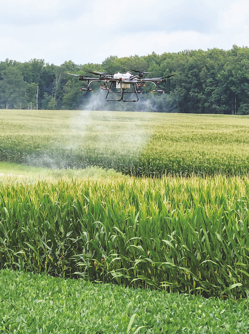
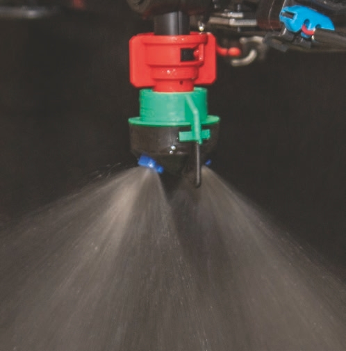
Using spray drones for agricultural, aquatic, mosquito, and rights-of-way applications are becoming popular tools in combating pests.
The Many Functions of Nozzles

Nozzles are used in an array of applications, including aquatic weed control.
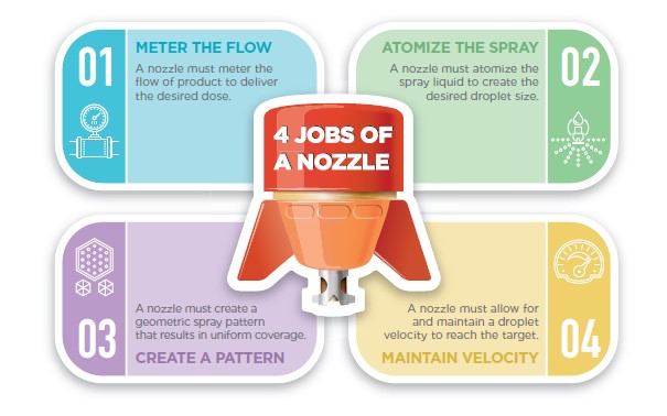
Nozzles are highly engineered equipment that are designed to meter, atomize, and create patterns to precisely apply the liquid in the sprayer tanks onto their targets. Applicators must carefully select nozzle type and design, nozzle spacing/positioning, and operating pressure for the travel speed and prevalent environment conditions to deliver effective pesticide doses to targets as efficiently as possible.
A first step toward appreciating the work spray nozzles perform is to define what nozzles need to do within milliseconds of the spray entering the nozzle body, exiting into the atmosphere, and landing onto the target. Nozzles must:
• Meter the flow to deliver desired doses
• Atomize spray liquid to create desired droplet sizes
• Create geometric spray patterns that uniformly cover the target
• Maintain droplet velocity to reach targets
Turn Liquid Streams into Droplet Clouds
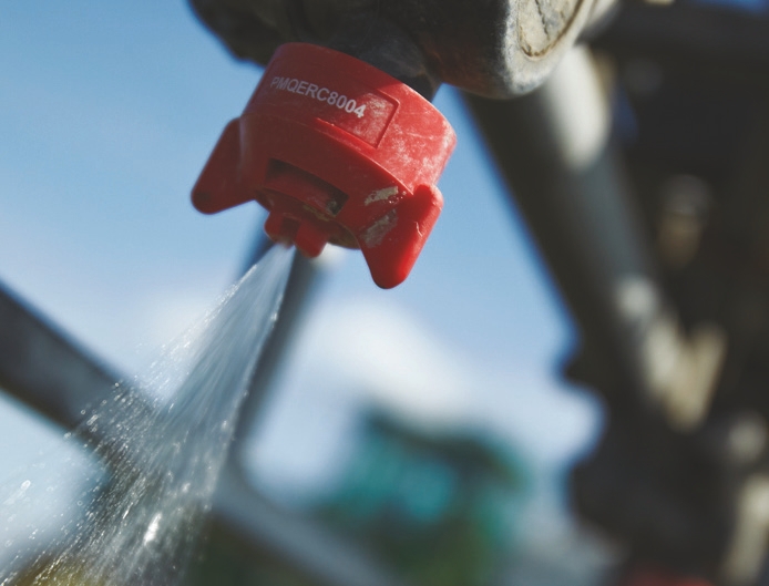
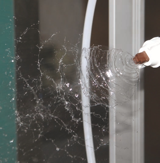
Atomization is the process of turning a liquid stream into spray droplets. In most instances, this conversion is produced when there is a high relative velocity between the liquid to be atomized and the gas (surrounding air) phase. For example, in commonly used hydraulic nozzles, a high-pressure pump pushes a liquid stream through a small orifice generating spray droplets released into ambient air.
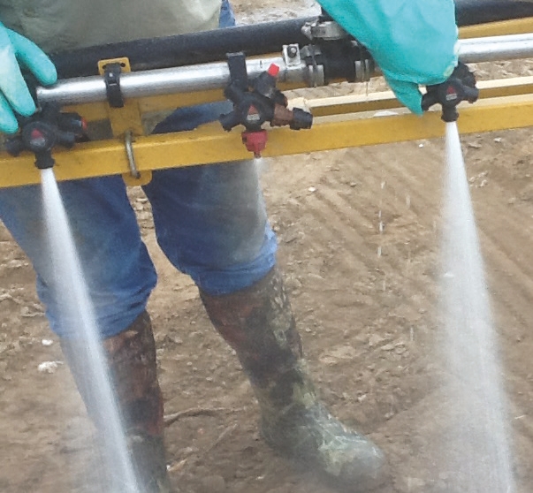
Without a nozzle, the water comes out like a water hydrant, which would serve no purpose in the application process.
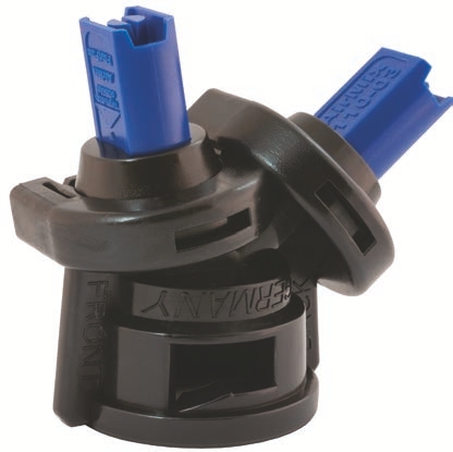
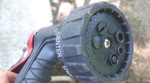
WHICH IS CORRECT: NOZZLE OR TIP?
People often use the terms “nozzle” and “tip” interchangeably, but there is a difference. The tip refers to the part inserted into a cap. It can be made of stainless steel, plastic, ceramic, or brass. The nozzle contains the tip and gets attached to the boom through the turret. In some sprayers, the distinction between the two is often difficult, because some nozzles and tips are manufactured as a single unit (such as, polymer nozzles). In such cases, the unit would be called a nozzle.
Imagine turning on an outdoor faucet connected to a garden hose. The wider you open the valve, the more water flows into the hose. Partially covering the end of the hose with your thumb decreases the orifice size, which breaks the stream into droplets.
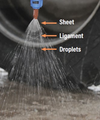
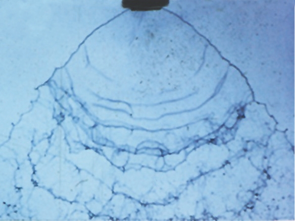
As the spray leaves the nozzle tip, the initial flow is a flat sheet of fluid. Once it leaves the exit orifice, the internal pressure no longer influences that sheet of water. As it leaves the nozzle tip and begins falling, the sheet of fluid begins to disintegrate into ligaments that will break into still smaller pieces of different sizes called droplets.
Two different nozzles working under the same pressure can produce remarkably different droplet sizes.
Create Droplets Within a Specific Size and Density
Pesticide applications are most effective when nozzles produce an optimum droplet spectrum with the correct carrier rate. Therefore, you should link your nozzle selection (including type and size) to the chemistry you are using, the carrier volume you’re applying, the surface the product is contacting, and the target pest. A specific droplet size spectrum may be an important factor to get the best activity from an herbicide, fungicide, and insecticide. That’s because different chemistries are most effective under different droplet spectrums. Unfortunately, very few pesticide labels give information about specific droplet sizes that will be best for a given application situation.
In general, fungicides require finer droplets and a higher density of droplets to provide better target surface coverage. Similarly, insecticides might need more fine or medium droplets to reach the undersides of leaves where the insects may be harboring. Systemic herbicides might work best with larger droplets in order to give the droplets more time on the target leaf surfaces for foliar absorption to occur before the water in the spray deposit evaporates.
Think how the target can influence droplet size selection. The optimum droplet sizes for specific targets and pesticide products must be considered together. In addition, some herbicides can severely injure sensitive crops and cause crop loss to neighboring areas if there is an off-target movement of the applied product. You can control such phenomena by paying attention to several factors in which droplet size distribution is the prime one. This helps explain why there are so many nozzle designs. Engineers are challenged to manufacture nozzles with droplet spectrums that fit largely within a narrow range of sizes (for example, very fine, fine, medium, coarse, very coarse, extremely coarse, ultra-coarse).
Nozzles of similar output (in this case 0.4 gallons per minute) can generate different droplet sizes that result in varying coverage on the target surface.
Form a Specific Spray Angle Width
For hydraulic nozzles, the spray angle is a static measurement of how wide the spray pattern will open up under a specific pressure. It is a function of nozzle designs, operating pressure, and the characteristics of the spray liquid. As the liquid goes through the exit orifice, the droplets conform to the physical shape of the nozzle, which then forms the angle. As the angle gets larger, the width of the spray pattern becomes wider. That provides more surface area to form spray particles, which results in smaller droplets. Common spray angles include 65°, 80°, and 110°, but the angle selection depends on the spraying equipment and nozzle spacing.
(Top) This nozzle has a 110° angle with a wide fan pattern. (Bottom) This nozzle has a smaller fan angle of 80°.
Create the Spray Pattern
There are nozzles with different spray patterns available on the market, and the right choice depends on the application type. The most common types of spray patterns are flat fan (tapered and even), cone spray, and solid stream.
• Tapered flat fan nozzles are designed to be used mainly in horizontal boom sprayers, because the deposition of the liquid has a tapered shape. The proper overlap of the adjacent sprays results in uniform distribution along the boom.
• Even flat fan nozzles do not require an overlap of adjacent nozzles for a proper distribution along the treated area. That is because these nozzles designed for banding pesticides (for example, over a crop row).
• Cone spray nozzles have hollow cone and full cone varieties. These nozzles are designed to be used in airblast sprayers, specialty crops, and directed spray applications.
• Solid stream nozzles are commonly used for fertilizer applications, but also in some right-of-way and aquatic applications.
To picture spray patterns in your mind, consider a garden hose nozzle. If you use the hose to directly apply water without any modification, good luck with coverage and retention of the water on a target. If you attach a turret sprayer onto the hose, you can create a number of adjustable water patterns to meet your specific needs, including flat fan, cone (full or hollow), solid stream, and wide angle. Each setting forces the water through a different nozzle that allows the flow pattern and droplet spectrum to change.
A turret garden hose sprayer has different spray patterns. Selecting the appropriate orifice allows you to perform various functions, including watering plants from a distance, gently misting shallow-planted seeds, or cleaning surfaces with a concentrated stream.

Meter the Flow of the Liquid
Nozzles control the flow rate, which is important because that determines the amount of pesticide applied to a given area and the application volume. Each nozzle is described by how many gallons per minute at a rated pressure it will deliver based on the size of the nozzle’s metering orifice. Smaller orifices have lower flow rates and larger orifices have higher flow rates. Operators can modify nozzle flow rates by changing the pressure within the system. Higher pressures increase flow rate and lower pressures decrease flow rate.
Control the Droplet Velocity
Droplet velocity measures how fast droplets are moving once they leave the exit orifice. Different nozzle designs, capacities, and operating pressures produce droplets with different velocities. Larger orifices or higher operating pressures mostly generate droplets that exit with higher velocities. Larger droplets can reach the intended target surface, but they can have the problem of bouncing off, splattering, or running off the target site.
Smaller droplet sizes normally correspond to lower velocities. Smaller droplets lose momentum quickly as they exit the nozzle, remain as droplets in the air longer, and can reach the target or be moved to non-target locations. Most estimates indicate that a fine droplet’s initial speed reduces by 90 percent within the first 3 feet. Weather conditions (such as wind speed) and travel speed directly influence the horizontal movement of smaller droplets. Air temperature and humidity also affect a droplet’s lifetime. Higher temperatures (greater than 86°F) and lower humidities (less than 50 percent) reduce the droplet’s lifetime. It goes without saying that nozzles are critical to the success of any spray application. While the types and costs of application equipment vary widely across the commercial application industries and agriculture, all equipment depend on nozzles to make successful applications.
The Push to Make Nozzles More Precise

Engineers studying fluid dynamics have long known that a spray entering and exiting a nozzle undergoes a complicated set of physical processes. In the early days of nozzle development, engineers were largely unable to document the processes involved in producing spray droplets with much accuracy. This resulted in a limited number of nozzles being used over a wide range of applications - a more of a one-size-fits-all approach.
It has only been in the last few decades that advances in our understanding of fluid dynamics have allowed spray nozzles to keep pace with improvements in application equipment and pesticide products. The “Factors Involved in the Evolution of Precision Nozzles” graphic indicates five factors that contributed to advances in nozzle precession.
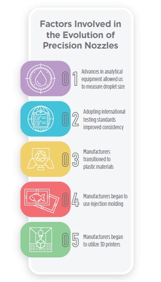
1. Advances in analytical equipment allowed us to measure droplet size
Advances in Analytical Equipment Measuring Droplet Sizes Engineers today are able to use analytical equipment that measure droplet size spectrum, spray angle width, droplet velocity, and flow rate more precisely and in ways unavailable to past generations. Incorporating advanced tools (such as engineering software, droplet size analyzers, 3D printers, and computational fluid dynamics) help manufacturers develop new nozzles. Increased computer processing and data storage, advances in laser diffraction, image detection, and computational mathematical software can now produce results in an afternoon that would have taken weeks or months to complete. Rapid, accurate, and reliable measurements of nozzle parameters and spray droplet characteristics have led to nozzles being designed, manufactured, and marketed for specific applications.
Developers use three techniques to measure droplets: image analysis, laser diffraction and phase doppler particle analysis. Image analysis and laser diffraction techniques are the mostly widely used.
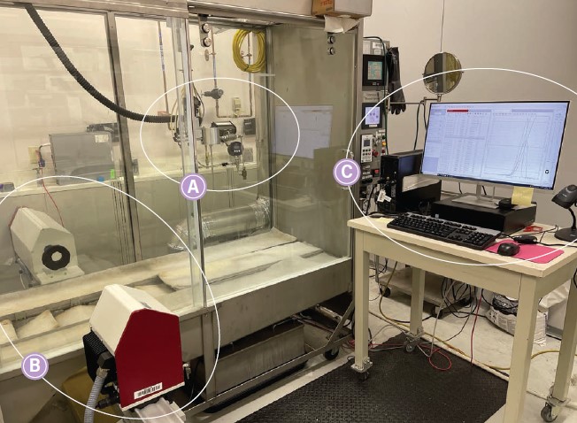
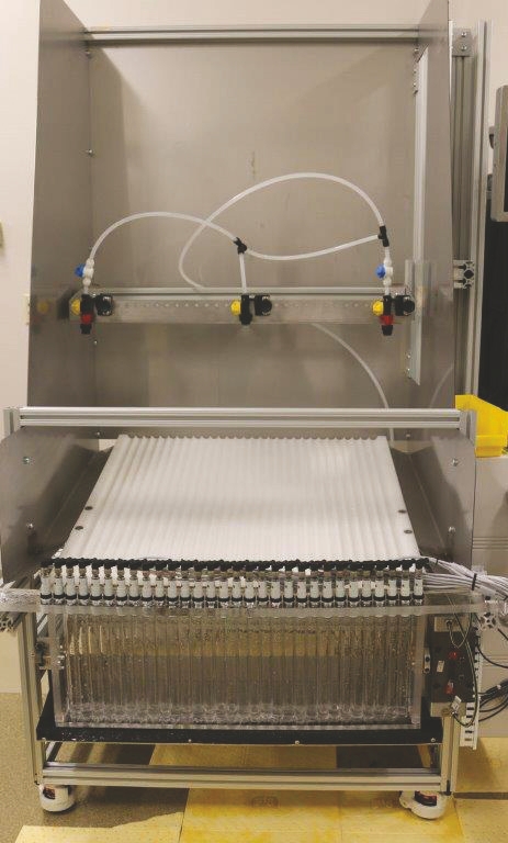
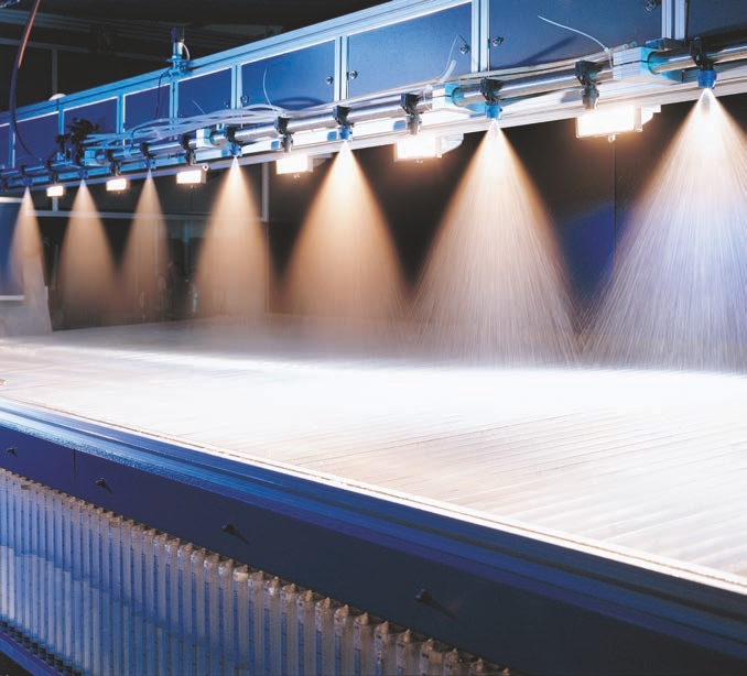
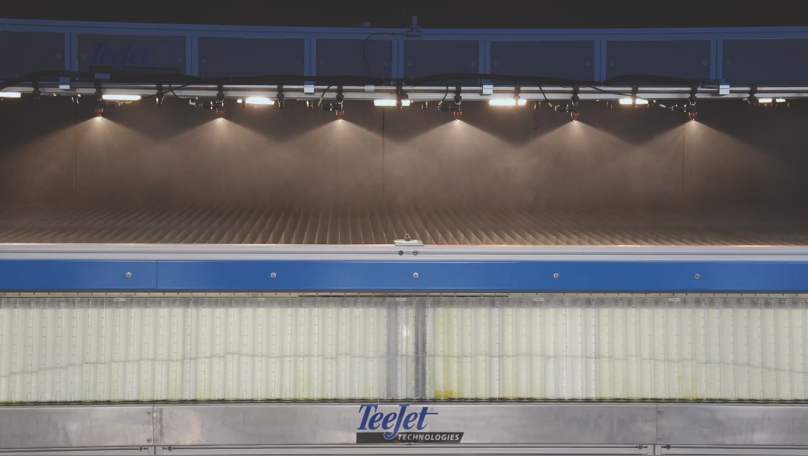
These photos show a laser diffraction spray chamber used to analyze spray droplets and patterns. The equipment includes (A) a nozzle mount; (B) a laser diffraction-based particle size analyzer; and (C) computer software for data visualization and analysis.
For image analysis, the analytical equipment images the spray pattern containing droplets of different sizes using a light source. The equipment software analyzes each image/snapshot in real-time to generate droplet size data. Some droplet size analyzers can also provide other pertinent information (such droplet velocity) by analyzing subsequent snapshots.
A RESEARCHER REMEMBERS THE ‘GOOD OLD DAYS’ OF NOZZLE RESEARCH
“I remember how very difficult it was to measure droplet size when I was a graduate student. “Today we have lasers, particle measuring lasers of all different types and sizes. And the data we can get out of them is phenomenal and in a very short period. It took my whole masters’ thesis to measure a droplet size, which I could probably measure today in less than 5 minutes. That quantum leap in measuring instrumentation has really allowed us to add some of those engineering parameters to nozzle development. “Now, nozzle manufacturers can make prototypes that they can run through the laser, and it can tell them what droplet size they are, and if they are close to their target or not and make changes going back and forth through the development phase. That has added to our ability to create nozzles of all different shapes and sizes and target applications in a ‘blink of an eye.’”
The Oxford Laser is one example of spray image analysis. It uses a camera (A) that detects droplet shadows (B). It then measures the droplet diameter in units called microns (1 millionth of a meter).
2. Adopting international testing standards improved consistency Acceptance of International Testing Standards
The instrumentation developers use to define and describe nozzle output created an emerging field of science with different testing protocols and nomenclatures with different meanings. However, manufacturers were generating results using different and unrelated testing protocols, making it difficult to compare one nozzle’s performance across manufacturers and sometimes even within a single company. In addition, the terms they used to describe those tests largely depended on how the nozzle manufacturer defined them. To standardize the playing field, various groups formed standard-setting committees. The groups included the American Society for Technical Materials (ASTM) International, Institute for Liquid Atomization and Spray Systems (ILASS), International Organization for Standardization (ISO), and American Society of Agricultural and Biological Engineers (ASABE).
These groups built consensus and manufacturers agreed to follow specific testing protocols when they created and marketed nozzles. Furthermore, this process standardized the definition of terms, which improved communication among university, government, industry researchers, and end users. In the long run, pesticide application industries and applicators benefited most from the standardization process.
Standards
It can’t be overstated how much creating standards advanced the fields of atomization research, nozzle development, and ultimately, nozzle selection by the end user. Gathering data using similar testing protocols allow us to design, develop, evaluate, and select nozzles for specific purposes regardless of the manufacturer.
3. Manufacturers transitioned to plastic materials
Transition to thermoplastic Materials
Years ago, nozzles were largely made from stainless steel and brass and produced by a rotary cutter. Those materials are still used today in some nozzles — mostly those that handle high-temperature liquids, have special designs, or under scenarios where abrasion resistance is critical. Today, most agricultural nozzles are made from plastics, which have several advantages.
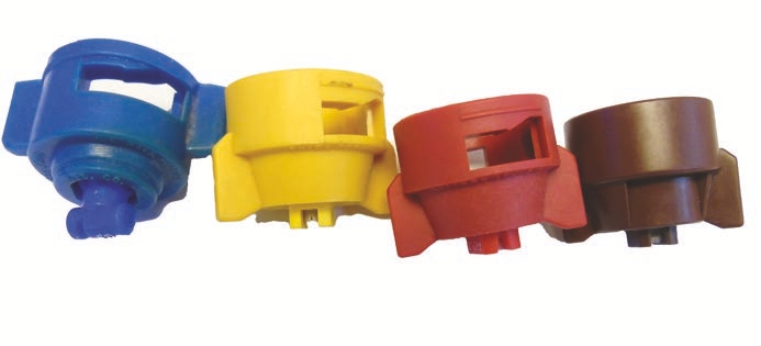
There are several advantages to using high-quality polymer-based plastics for agricultural spray nozzles. From a design and engineering perspective, plastic enables manufacturers to create new designs to have internal and external customization that cannot be duplicated in metal. From a manufacturing perspective, polymer nozzles can be produced with a high level of precision and in large quantities to meet consumer demand. From a farmer or industry perspective, polymer spray nozzles provide a cost-effective, corrosion- resistant solution with multiple nozzle types and droplet sizes — they are also color-coded for easy identification.
4. Manufacturers began to use injection molding
Use of Injection Molding
Injection molding, the process of using high pressure and temperature, forces melted plastic into metal molds. The metal molds provide efficient and consistent production and offer designers the freedom to create product shapes and geometries that would otherwise be difficult, cost prohibitive, or potentially impossible to produce using other methods or materials.
Injection molding resins can vary in strength, durability, heat resistance, impact, and chemical breakdown. they can accurately and repeatably be dyed, which allows manufacturers to color-code completed parts and products.

Through a computer simulation, an engineer can quickly modify a design and see how the nozzle might react to those modifications. It is a way to virtually develop new designs instead of having machinists (or even 3D printers) repeatedly build and rebuild prototypes.
5. Manufacturers began to utilize 3D printers
Utilization of 3D Printers
At one time, skilled machinists were required to create prototype nozzles. After researchers tested the nozzles, the machinists would have to modify and reconstruct the prototype. Nozzle manufacturers now can rely on designing and testing nozzle prototypes with 3D printers. Once prototypes meet the desired specifications, they will undergo standard testing protocols. After testing, 3D printers enable manufacturers to make injection molds that can accurately mass-produce the new designs. Nozzle manufacturers increasingly rely on designing prototypes with 3D computer simulations. Computational fluid dynamics is a field of study that allows companies to use computers to measure the impact of design changes before making prototype nozzles.
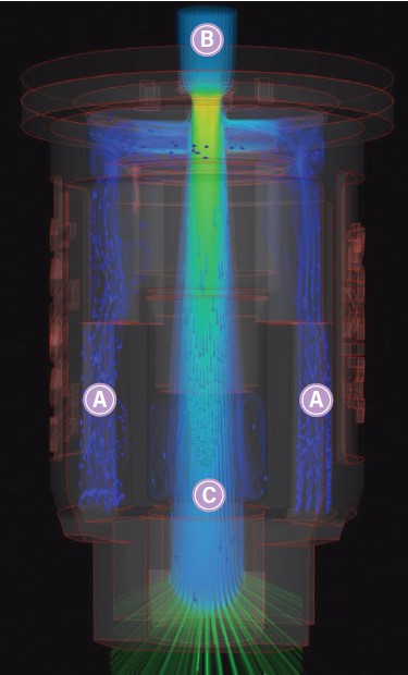
These graphics show how computer simulations can test nozzle designs. (Top) The blue (A) represent air coming from the inlet and going to the mixing chamber where it will mix with the liquid. (B) This design has a pre-orifice with a small diameter to increase liquid velocity (the yellow represents greater liquid velocity). The liquid and air combine in the mixing chamber (C).
The colors in this illustration indicate droplet size. Warmer colors (red and orange) represent coarser droplets; cooler colors (blue and green) represent finer droplets.
Characterizing Droplet Size and Spray Pattern
To better understand what nozzles do under specific work conditions, we must consider the:
• Diversity of spray equipment
• Impact of droplet size on pesticide efficacy
• Application volume per area
• Shape of the plants and surfaces that will be sprayed
• Target pests
• Marketplace competition
• Applicator and customer expectations
• Potential environmental and legal penalties for off-target movement
Decades of testing and field use ultimately determine how specific droplet spectrums work for certain pesticides. A nozzle might need to produce smaller droplets for uniform coverage (such as for fungicide applications). Or a nozzle might need to compensate for spray drift concerns by producing larger droplets (such as for herbicide applications). In other cases, a set of nozzles might need to move to higher volumes because of higher application speeds. This would require a nozzle with a bigger orifice to achieve the higher flow rate. Another application might require much less volume, requiring a smaller orifice nozzle with a lower flow rate.
COMMON MEASUREMENTS FOR NOZZLES
Here are some terms that are commonly used to describe nozzle characteristics that will help with the nozzle selection process.
• Volume median diameter
• Droplet size distribution
• Droplet velocity
• Driftable fines
• Relative span
• Flow rate
• Spray angle
• Lateral distribution
• Pattern shape
Droplet Size and Distribution
Today, there is a wide variety of agricultural nozzle designs, some intended for specific and limited circumstances. For a pesticide label or consultant to prescribe the right nozzle for a job, we need a way to describe nozzle features and distinguish between types. This level of precision implies a level of specificity when manufacturers select nozzles to perform the tasks they are designed to provide.
Manufacturers need to be able to answer these questions about a nozzle:
• What is the volume median diameter (VMD) of the droplet spectrum?
• What is the droplet size distribution (also called, droplet spectrum)?
• What spray classification does it produce at different spray pressures (such as fine, medium, coarse)?
• How uniform is the droplet size distribution (known as relative span) in the spectrum?
• What is the velocity of those desired droplets when they exit the nozzle?
The average size of droplets and their distribution (spanning from smallest to largest diameters) primarily depends on how a nozzle atomizes the spray liquid. As mentioned earlier, many factors influence the droplet spectrum, including operating pressure, the nozzle’s internal configuration, the size and shape of the exit orifice, the spray angle, and the chemical properties of spray liquid (such as, density and viscosity).
While different spray tips can produce the same flow rate (for example, gallons per minute), the droplet sizes making up that flow can still vary dramatically when they are influenced by the factors mentioned above. This is why manufacturers test each nozzle type at different pressures to determine the median, average, and distribution of droplet sizes, as part of nozzle classification.
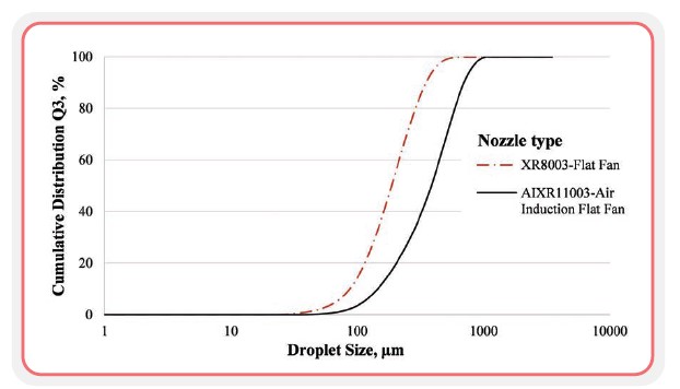
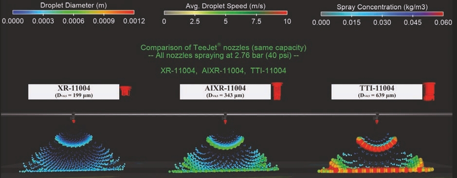
This figure illustrates changes in the cumulative distribution of particles based on two nozzle types with the same capacity (flow rate) at 40 PSI pressure. You can observe a greater cumulative distribution of small droplets for an XR nozzle compared to an AIXR nozzle.
Nozzles produce a range of droplet sizes. Knowing that range has important implications when you evaluate and select a nozzle. If you plan to use a nozzle in an area where off-target movement of spray droplets or spray drift is a concern, you should choose a nozzle that minimizes the volume of finer droplets (or, driftable fines in the spectrum).
There is not one specific size that determines which droplets will drift or not. Wind velocity at application time plays the ultimate role in defining the cutoff droplet size below which are considered driftable. However, under normal wind velocity conditions, droplets smaller than 150 microns are considered driftable.
Conversely, you might select a nozzle that produces a large proportion of small droplets (for example, fine and very fine) when applying a fungicide to a vineyard with an air-assisted sprayer or if you are spraying for a community-wide mosquito control program that must produce small droplets that remain in the air long enough to contact mosquitoes.
The software associated with different analytical techniques categorizes droplets into three common diameters variables:
1. Dv0.1 (also called Dv10 or D10)
2. Dv0.5 (also called VMD, Dv50, or D50)
3. Dv0.9 (also called Dv90 or D90)
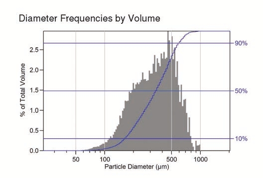
Dv is an abbreviation for diameter volume. These diameters are commonly measured in microns or micrometers (μm). There are 125,000 microns in one inch. For reference, the diameter of human hair is typically 75 to 100 microns. Dv0.1 is a value where 10 percent of the total volume of liquid spray flux is composed of droplets with diameters smaller than this value. For example, a Dv0.1 of 99 means that 10 percent of the droplets the nozzle produces will be smaller than 99 microns.
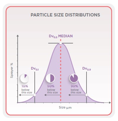
Spray clouds created from the atomization of the solution from the spray tips results in a droplet size distribution in a bell-shaped curve. Extensive research and development is placed on narrowing this curve to have relatively fewer fine droplets that may never hit the target, or excessively large droplets that may bounce off target leaves or reduce spray coverage.
Dv0.5 is a value where 50 percent of the total volume of liquid spray flux composed of droplets with diameters smaller than this value. For example, Dv0.5 of 203 means that 50 percent of the droplets the nozzle produces will be smaller than 203 microns. Some people also refer to the Dv0.5 value as VMD (volume median diameter). Technically, the two terms are not exactly the same, but are very close in most cases. Therefore, they are often used interchangeably. ISO Standard 5681-2020 defines Dv0.5 as an equivalent value to VMD.
Dv0.9 is a value where 90 percent of the total spray volume of liquid spray flux is composed of droplets with diameters smaller than this value. For example, a Dv0.9 of 417 means that 90 percent of the droplets the nozzle produces will be smaller than 417 microns. Different nozzles that have the same flow rates may have very different Dv0.1, VMD, and Dv0.9 values (as illustrated in this table).
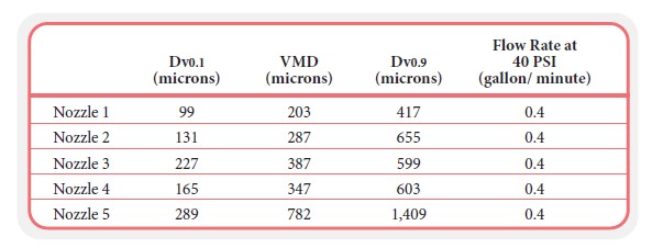
The VMD for Nozzle 1 is 203 microns (μm in metric units), which means that 50 percent of the total volume of liquid it sprays is composed of droplets with diameters smaller than 203 microns; the other 50 percent of the droplets are larger than 203 microns. On the other hand, the VMD for Nozzle 5 is 782 microns. Although nozzles 1 and 5 have the same flow rate, they are very different from the droplet size perspective. Nozzle 5 produces larger droplets while Nozzle 1 produces smaller droplets. Based on the Dv0.1 of Nozzles 1 and 2, we can observe that 10 percent of the volume of the spray is contained in droplets smaller than 99 and 131 microns, respectively (the rest of the spray produces larger droplets). Smaller Dv0.1 values indicate the driftable droplets a nozzle can produce. The Dv0.1 for Nozzles 3, 4, and 5 are relatively larger than Nozzles 1 and 2. This may indicate that, under the same pressure, Nozzles 3 through 5 produce a smaller volume of driftable fines than Nozzles 1 and 2. Among the five nozzles, there are also large differences in the Dv0.9. Nozzle 1 presents the smallest Dv0.9, which means that 90 percent of the volume of the spray is composed of droplets smaller than 417 microns.
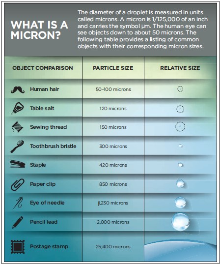
A micron represents 1 millionth of a meter, or a little more than 1/25,000s of an inch.
The differences in droplet sizes between nozzles are neither good nor bad, they are just different. The optimal nozzle for a given application depends on the requirements needed for that application. VMD values provide a general overview of what to expect from the droplet spectrum. Evaluating a nozzle’s droplet spectrum includes reviewing all three droplet size distribution values. Nozzle 5 with its larger droplet spectrum across the Dv0.1, VMD, and Dv0.9, indicates it would be an excellent drift reduction nozzle. However, if getting a uniform distribution on the target surface is the goal, Nozzle 5 might not be the best choice for that application, because the majority of the spray volume is composed of coarser droplets. Conversely, Nozzle 1 has a fine droplet size spectrum with more of the spray volume contained in smaller droplets compared to the other nozzles. The lower Dv values for Nozzle 1 predict it would provide the greater coverage required for an effective fungicide application. However, it would be less of a candidate to apply systemic herbicides if off-target movement or spray drift is a prime concern.
Droplet Sizes Correspond to Color Codes
ISO (ISO 25358 and prior versions) and other standard-setting organizations developed droplet size classifications. The Dv0.1 and the VMD values categorize droplets from extremely fine to ultra-coarse. Instead of providing the values for Dv0.1 and VMD, nozzle manufacturers follow a droplet size color-coding scheme (according to the ISO standard). This color-coded scheme makes it easier for users to understand.
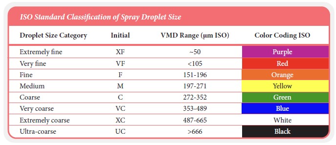
It is important to highlight that droplet size varies with pressure range, nozzle capacities, spray angle, and pesticide formulations. The droplet sizes manufacturers place on their products are based on tests with water. It should be noted that the color scheme for droplet size categories is not related to the color scheme used for indicating nozzle orifice size. The VMD was applied to the five nozzles to describe spray droplet characteristics in the following table.
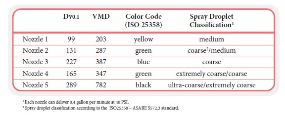
These are 5 nozzles were tested for data collection (Dv0.1 and VMD), and then categorized into the ISO approved color code and droplet size class.
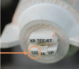
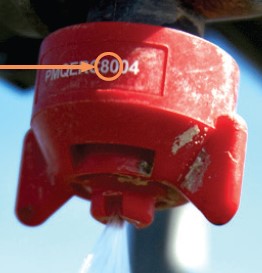
On the table below, we can compare the droplet size of the XR TeeJet® Extended Range nozzles that are available in two angles: 80º and 110º. The table outlines how spray angle, pressure, and orifice size impact droplet size.
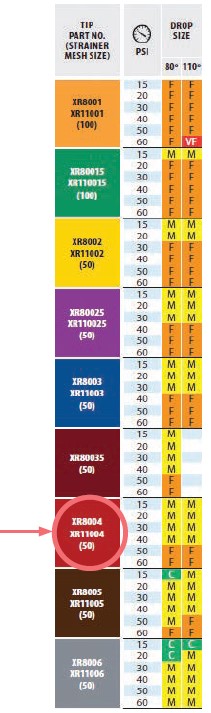
Let’s use the XR8005 nozzle (taken from the TeeJet® nozzle catalog 52) as an example. This nozzle has an 80° spray angle and produces a coarse, medium, and fine droplet spectrum depending on the pressure. Notice that the 110° spray angle produces fine to medium droplets by changing the pressure. When a spray liquid exits an orifice, a higher fan angle creates a wider pattern and area to disperse the droplets. At the same time, a greater degree of atomization leads to a greater number of smaller droplets. This can be explained by the same flow volume of spray solution being required to cover a larger (wide angle) or smaller (narrow angle) area. It takes more droplets to effectively cover a larger area with the same application volume.
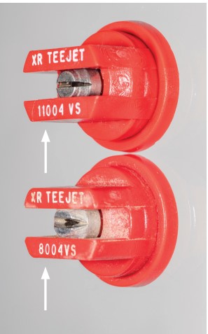
These two nozzles have the same flow rate of 0.4 gallons per minute at 40 PSI. The difference between them is the spray angle. The one on the left (XRC 8004) has a spray angle of 80°, while the one on the right (XRC 11004) has a spray angle of 110°. Never mix nozzles with different spray angles on the boom. Doing so results in improper pattern overlap, which leads to non-uniform spray coverage across the boom.
Driftable Fines Are Less Defined
Today’s software can measure smaller droplets linked to spray drift. One of the first and most extensive attempts to correlate spray droplets to pesticide drift was performed by the Spray Drift Task Force, a group led by the pesticide industry. The task force compared exit orifice openings, pressures, nozzle designs, and nozzle heights from targets to measure how much of the total volume of a spray moved off-target and how far downwind the sprays moved. The problem with small droplets exiting a nozzle is they often do not have enough mass or energy to reach the target. Theoretically, this means those droplets remain in the air longer, which makes them susceptible to being moved off-target by the wind.
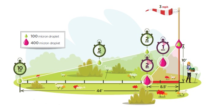
For example, a 100 μm droplet may take 10 seconds to fall a vertical distance of 10 feet and can move 44 feet laterally at the same time when there is a 3-MPH wind. By contrast, a 400-micron droplet released from the same height can fall 10 feet in 2 seconds and will only move 8.5 feet laterally when there is a 3-MPH wind.
Nozzle manufacturers use the Dv0.1 as a surrogate for spray drift potential by using a value called percent of driftable fines. The percent of driftable fines can be expressed as an equation:
Percent of driftable fines = fraction of total spray volume contained in droplets < a given value assigned by the manufacturer for comparison there is no consensus or agreed-upon standard of what constitutes driftable fines.
University and industry researchers typically use a percent volume of less than 100 microns, 141 microns, or 150 microns as the cut-off values for driftable fines. While there is no defined value for driftable fines, there is a widespread agreement that going from a fine to a medium to a coarse spray reduces the relative risk of physical spray drift. However, boom height and weather conditions can make significant differences in what stays on or moves off target.
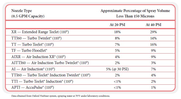
The following table shows how increasing the pressure from 20 PSI to 40 PSI produces higher percentages of smaller droplets (for example, 150 μm) with a selection of nozzles. For some nozzles, the pressure change causes a rather dramatic change in the percentage of smaller droplets produced. The opposite is also true: reducing the operating pressure reduces the driftable fines.
BEWARE OF DRIFT!
Droplet size can greatly impact where spray could land. Know the conditions and what to expect before you spray.
Spray Droplet Uniformity Measured by Relative Span
A unitless value known as relative span (RS) provides details about the uniformity of the droplets exiting a nozzle. The formula for RS is:
relative span = (Dv0.9 - Dv0.1)/Dv0.5
Relative span is more about describing the uniformity of droplets a nozzle produces. A relative span is calculated as zero (0) if every droplet coming out of the nozzle is the same size (had the same Dv0.1, Dv0.5, and Dv0.9 value). Let’s assume the value for the three DV categories was 300 microns, then:
relative span = (300 – 300)/300 = 0
An RS of zero indicates the diameters are the same for all droplets in the spray cloud. It is impossible to make an agricultural nozzle that produces 100 percent of the droplets at the same size. But what that tells us is that the lower the RS value, the more uniformity there is in the size of the droplets being produced. If we use the previous five nozzles (from page 37), we can calculate their RS values.
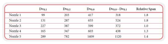
Note that Nozzle 3 has the smallest RS (1.0), meaning the droplet size diameters of all the droplets it produces are most similar. Conversely, Nozzles 1 and 2 have the greatest RS (1.8), indicating that these two nozzles (compared to the others) produce the least uniformity in droplet size, which may increase drift and/or reduce spray coverage (an extremely important attribute for contact-type pesticides).
Therefore, when selecting nozzles pay attention to both the VMD and the RS values (if the data to calculate the RS are available). The ways that test results are displayed can depend on the type of droplet size analysis equipment and techniques that are used. However, most reports will include the Dv0.1, Dv0.5, Dv0.9, and RS. The information presented in the table below was generated using one particular droplet size analysis equipment (Oxford), which is also capable of determining the velocity (in meters per second, or m/s).
Flow Rate
Flow rate measures how much liquid is going through a nozzle over a given time - primarily gallons or liters per minute. At a manufacturer’s site, a nominal nozzle flow rate is typically measured at 40 PSI with water at 70°F. The nozzle is primed and operated continually while the output is measured for an established time interval.
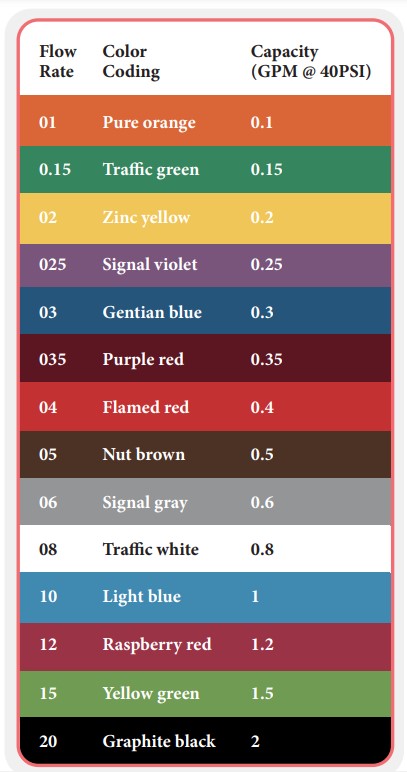
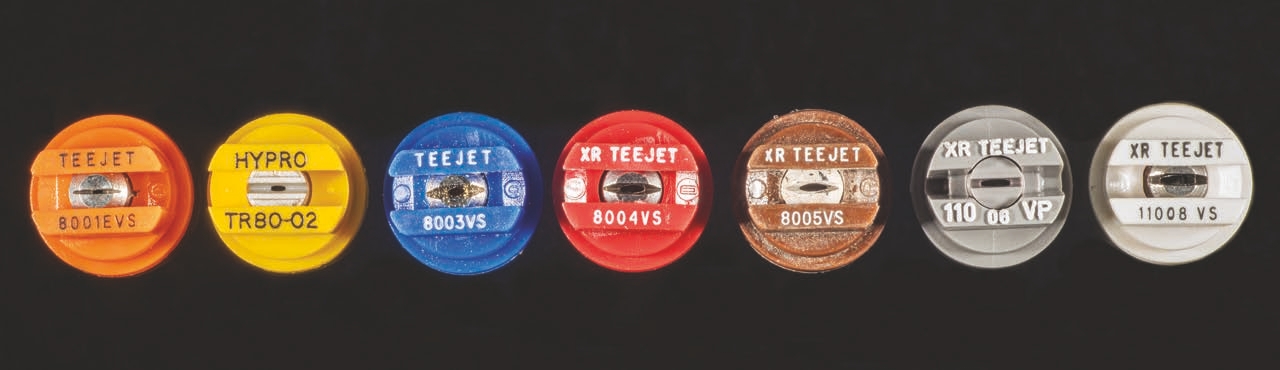
Flow rates follow an international standard color- coding system (ISO 10625), in which each color represents the flow rate of a nozzle at 40 PSI (2.8 bar). Manufacturers use this color-code to dye plastic nozzles and make it easier for end-users to identify which nozzles they are using. For example, yellow nozzles indicate a flow rate of 0.2 gallon per minute, a blue nozzle 0.3 gallon per minute, and a red nozzle 0.4 gallon per minute at 40 PSI.
In these examples, flow rate is independent of nozzle design and manufacturer. Over one minute, a red cone, a red flood nozzle, and a red air induction nozzle will all deliver approximately 0.4 gallon at 40 PSI.
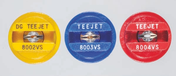
It is important to note that this flow rate color scheme is completely separate than the colors used for characterizing spray droplets from extremely fine to ultra- coarse. The table to the right provides the current flow-rate color-coding system with examples shown below.
Spray Angle
Spray angle is a geometric measurement taken at the exit orifice. Higher pressures produce wider spray angles. The spray angle for a specific nozzle is determined at different operating pressures. It is calculated at its lowest pressure to define whether the spray angle is 110°, 80°, or some other angle.
Most nozzles list their spray width angles as part of their descriptions.
Using the lowest pressure to define the spray angle helps ensure that the sprays overlap correctly. Users can adjust spray overlapping by changing the distance from the target.
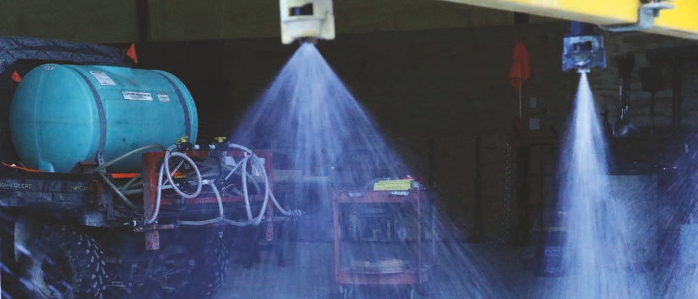
(Below) A 110° nozzle in use. Both a 110° and 80° spray nozzle are predicated on the width of the exit orifice.
Lateral Distribution
Lateral distribution describes the uniformity of the volume that a nozzle distributes as measured by a distribution table (this is also called a patternator). This measurement provides a lateral footprint for the nozzle for how the volume is distributed along the spray boom. Manufacturers measure lateral distribution with a spray table that is divided into sections. Manufacturers mount a nozzle or set of nozzles to a spray boom and then collect and measure an amount of water in each of the slots. When developing nozzles, manufacturers want each nozzle to maintain a specific distribution (that is, pattern) throughout the nozzle’s recommended pressure range. Aside from pressure, other factors affect lateral distribution. Spray angle, spray pattern, application height, nozzle spacing on the boom, nozzle wear, clogged nozzles, nozzle quality, and a spray liquid’s physical properties can all influence lateral distribution. Manufacturers need to generate measurements pertinent to lateral distribution at different pressures, different heights, and different spacings. Critical for the design of any new nozzle is that it produces a uniform lateral distribution across different variables.
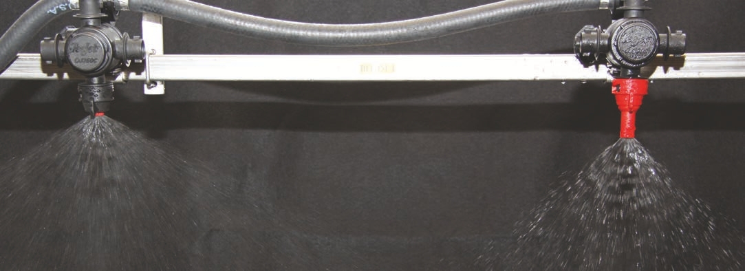
The front view (top) and side view (below) of two patternators show nozzles spraying into plastic compartments where their output will be measured. Lateral distribution is an important measurement to determine the proper overlap required between nozzles.
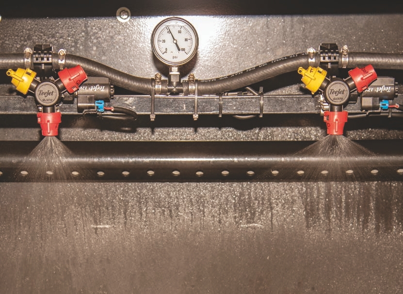
This photo shows an instrument measuring the lateral distribution of a Turbo TeeJet® nozzle with a 110° fan angle and a flow rate of 0.4 gallon per minute. The measured CV is 2.4 percent. Visually, you can tell the nozzles are spaced correctly, because the amount of water collected is almost the same from each nozzle, except for the end nozzles where there was no overlap.
While the spray tables allow you to visually evaluate how uniformly a nozzle sprays, engineers have used a statistical parameter known as coeffcient of variation (CV) to determine a quantitative way to measure uniformity across the treated area. The CV provides a numerical value of how much spray uniformity on the target varies across the width of the spray. A perfect CV is zero, because you have no variation across the cells collecting the spray. High CV values indicate a lot of variation; low CV values indicate more uniform distribution. Each company sets its own internal threshold for CV value. According to the ISO 16122-2 standard, good quality of the distribution along the treated area must present a CV value no greater than 10 percent. For example, the Julius-Kuhn Institute in Germany considers a nozzle set has an acceptable distribution when its CV is less than 7 percent.
Environmental Impacts
Manufacturers largely measure and test nozzles under controlled conditions. It is important to recognize that changing field conditions during spray applications can positively or negatively influence nozzle performance. It is beyond the scope of this publication to discuss these in detail; however, these factors can play important roles in modifying a nozzle’s efficiency and performance:
• Sprayer travel speed
• Wind speed
• Wind direction relative to the sprayer travel direction and sensitive off-target species
• Air temperature
• Time of day for pesticide application
• Temperature inversions
• Air relative humidity
• Chemistry of the spray solution
• Boom spray height
• Pesticide label directions
Construction Materials and Adaptive Designs
After 2,4-D herbicide was introduced in the late 1940s, it sparked the development of new nozzle designs. Since then, the rate of changes in nozzle designs have been increasing, often making earlier designs obsolete. This reflects the increasing numbers of new pesticide formulations, advances in spray equipment technology, and new methods in nozzle design and construction. It may come as a surprise that nozzle design requires a tremendous amount of research, engineering, and technology. Most do not realize that even minute design changes can produce major changes in nozzle performance. Nozzles are relatively small, but highly sophisticated and important pieces of application equipment. Their compact internal spaces require tremendous accuracy with tolerances of 1/10,000 of an inch. Consider the challenge to engineers as they develop and alter nozzle designs. Do they want the nozzle to be a generalist? Or do they need a design that must contend with a very specific set of working parameters?
There are many questions that nozzle designers ask:
- Should the orifice be smaller or larger?
- What materials should the nozzle body be made of?
- What materials should the tip be made of?
- Should the spray tip be longer or shorter?
- Do multiple exit orifices affect droplet size?
- Can we place a metal or plastic platform under an exit orifice?
- Does the angle of that platform influence droplet size and pattern distribution?
- Where is it best to place air induction ports?
- What will a mixing chamber do to spray droplets?
- How large should the air induction port opening be?
- What screen strainer size will protect the nozzle tip from clogging?
- Can the nozzle cap fit current application equipment?
The materials that nozzles are made from affect their weight, durability, and cost. Internal plumbing affects the pressure and flow rate of the liquid as it moves through a nozzle. The size, shape, and orientation of the exit orifice affects spray shape and spray droplets. The size and shape of the nozzle itself will determine how it mechanically attaches to the sprayer and how it responds to environmental factors like wind and temperature.
All this and more goes into the nozzle development process. Engineers develop, test, and retest prototypes until the design satisfies the requirements. Let’s look more closely at some of these factors.
External Dimensions
The sizes and shapes of nozzles (inside and out) influence the characteristics of the sprays they discharge. For example, some nozzles are longer to incorporate air injection ports. Some nozzles need additional girth to accommodate mixing chambers, or channels, which must be balanced against the designs of nozzle caps. Entrance Orifice Meters Liquid into Nozzle Nozzle designs can alter initial flow rates and droplet sizes by manipulating entrance orifices. For some nozzles, liquid flows into the entrance orifice and then proceeds directly to the exit orifice. In others, designers place a rubber, ceramic, or plastic cap with one or more holes of different sizes and chambers. These modifications help set up the turbulence of the spray entering the nozzle’s main body where an internal mechanism works to determine the final size of the spray droplets when the liquid sheet exits the final orifice.
Nozzle manufacturers can make numerous modications at the entrance orifice to affect flow rate and droplet size spectrum.
Structural Modifications Within a Hydraulic Nozzle
Hydraulic nozzles rely on energy in the form of liquid pressure to force spray liquid out through the exit orifice. The designs produce a moderate rate of flow and a wide range of spray shapes and droplet sizes. While entrance orifices meter flow, exit orifices define spray geometry (shape) and droplet sizes (spray quality). It is remarkable that relatively tiny design changes can have large impacts on performance, and it takes milliseconds for the spray atomization process to complete - from the time the spray liquid moves into the entrance orifice and is expelled out of the exit orifice. In recent times, most nozzle designs have focused on producing consistently larger spray droplets to reduce the likelihood of particle spray drift. Such nozzles often feature internal metering pre-orifices that meter the amount of liquid flowing into the nozzle. These areas are then followed by a reduction in the internal operating pressure and produce larger spray droplets than conventional that fans at the same boom pressure.
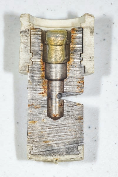
This nozzle cross-section reveals it has increasing smaller chambers before a liquid exits the orifice. This intentional compression of liquid forms specific droplet sizes.
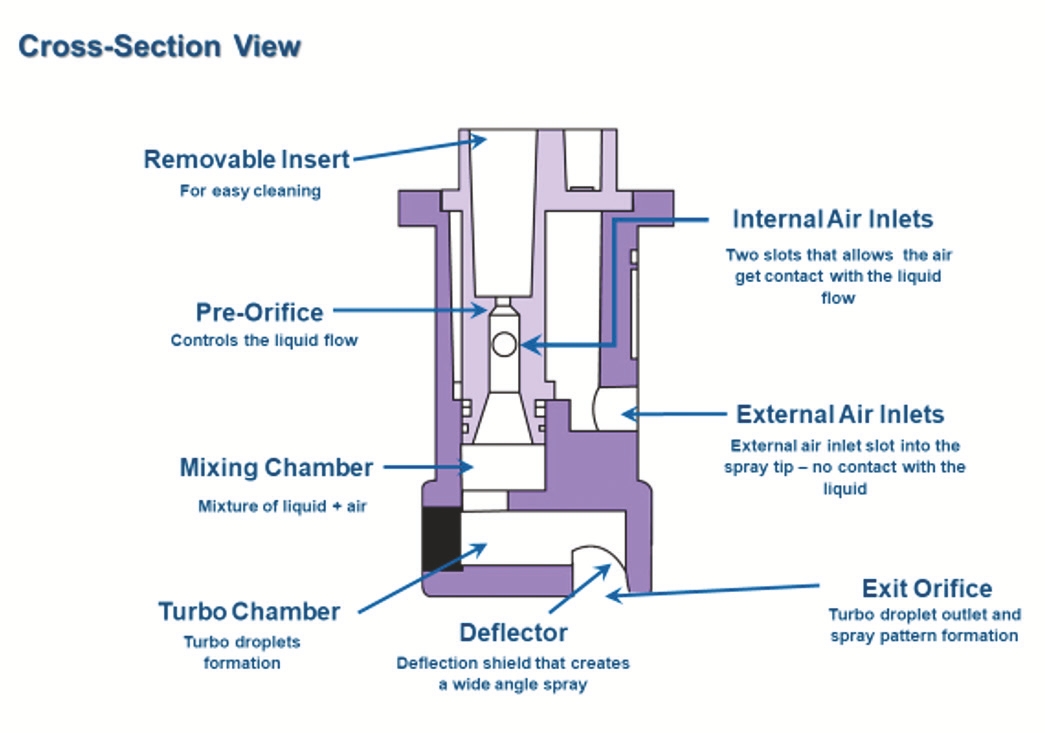
This illustration shows a cross-section of a nozzle and all the parts that allow it to deliver unique characteristics.
Structural modifications can include different cavities, chambers, and tunnels that the spray liquid is forced through. Altering the flow and pressure inside nozzles helps determine the droplet spectrum as liquid sheets pass the exit orifices. In drift reduction nozzles, exit orifices are larger than pre-orifices, which reduces spray pressure and produces larger droplets. One way to modify a nozzle internally is by using an air induction or Venturi design. Such nozzles pull in air, which reduces pressure on the liquid and produces larger droplets that exit the nozzle. Some manufacturers suggest that air bubbles trapped in the resulting droplets promote shattering and secondary coverage when droplets contact targets. Depending on the design, these nozzles must be operated at higher pressures than conventional tips.
This illustration shows air inlets that bring air into the nozzle to increase droplet size.
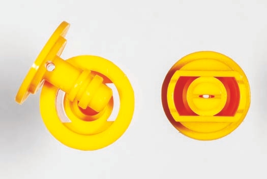
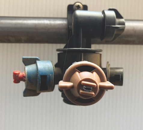
This photo shows an air induction nozzle with entry ports at the bottom on the tip.

The arrows point to the air induction ports on a 0.4 (red) and 0.3 (blue) gallons per minute nozzles.
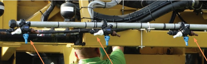
(Top) This boom is equipped with air induction nozzles with nozzle bodies equipped with different flow rates (blue, white, brown).
This nozzle draws air from near its exit orifice that allows the air to enter the chamber.
A second type of internal modification is called the turbulence chamber. The chamber is a cavity between the pre-orifice and exit orifice. When spray liquid passes through the pre-orifice, it enters the chamber where turbulence slows the liquid, reduces its energy, and facilitates the creation of larger droplets upon leaving the exit orifice.
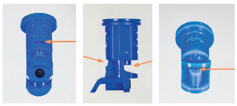
Structural Modifications to the External Exit Orifice
As previously discussed, the exit orifice appears to be a simple modification with one or more slots cut into the nozzle. Given that the exit orifice can define the spray pattern, width, flow rate (for some nozzles), and droplet cloud, it should not be surprising that this part of the nozzle has undergone numerous design changes over time.
Many manufacturers have modified the exit orifice to influence spray angle width and droplet size.
Materials Used in Nozzle Tips and Bodies
Materials used to make nozzle tips include brass, plastic (polymer), stainless steel, and ceramic. There are many questions engineers consider when deciding which materials to use, including:
• Will the tip spray abrasive or corrosive materials?
• What pressures will the nozzle be operated under?
• How small will the nozzle be?
• How many units will be sold?
• What will be the unit cost of with one material over another?
• How difficult will it be to produce the nozzle?
EVALUATING NOZZLES FOR RESISTANCE TO ABRASION AND CORROSION
Manufacturers test for nozzle wear using an accelerated test. They do this by continuously passing an abrasive material (like quartz and clay) through the nozzle for defined period. At the end of the test, manufacturers evaluate the nozzle to see if the flow rate and distribution pattern have changed. In this way, they can obtain results in a few days or weeks depending on the material being tested.
Corrosion is more difficult to test in the laboratory. The amount of corrosion is largely determined by the concentration of the material in the spray. If corrosion occurs, it happens over a longer period than the effects observed from the abrasion test. Characteristics associated with corrosion include rust and the nozzle material becoming brittle. Nozzle manufacturers work with the pesticide manufacturers to work out the details about the compatibility of the products with the common materials used in nozzle construction.
There are two categories for the materials used to manufacture spray tips and nozzle bodies:
1. Metals
2. Nonmetals
Metal nozzles, such as those of brass and stainless steel, are manufactured by computers that control a laser that cuts the nozzle out of a block of the material. Once the nozzle is made, it then goes to a machine that cuts the exit orifice slot and drills the hole. Spray tips manufactured by lasers are said to be more precise because of the computer-driven technology.
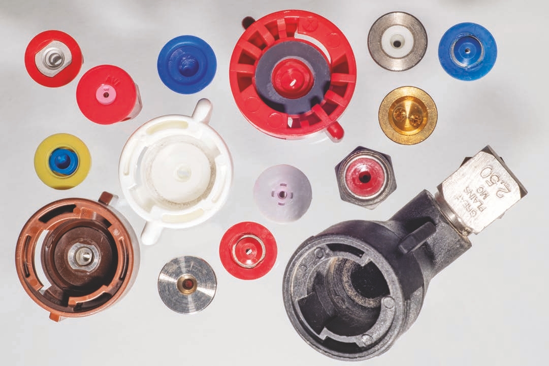
Ceramic and plastic tips are manufactured through an injection molding process. Manufacturers heat the solid material to a liquid phase, and then force the material into specifically designed molds. The material in the mold is allowed to cool and solidify. As the material cools, it shrinks slightly. Compared to metal tips, plastic and ceramic tips are less precise from one nozzle to the next, so they have slight variations in flow rate and droplet size. However, the precision gap between metals and nonmetals has become less noticeable over time because of refinements in the manufacturing processes. The advantage of polymer and ceramic tips is that they are mass produced, which can lower cost. It is a common misconception that by looking at most nozzles people may think that they all are made from plastic. What stands out in a nozzle is the colored polymer component (that is, the plastic nozzle body), but the tip inserts can also be made of stainless steel and ceramic.
(A) An all-stainless-steel nozzle with a plastic color-code belt.
(B) A polymer tip built into a plastic nozzle.
(C) A ceramic insert built into a polymer nozzle.
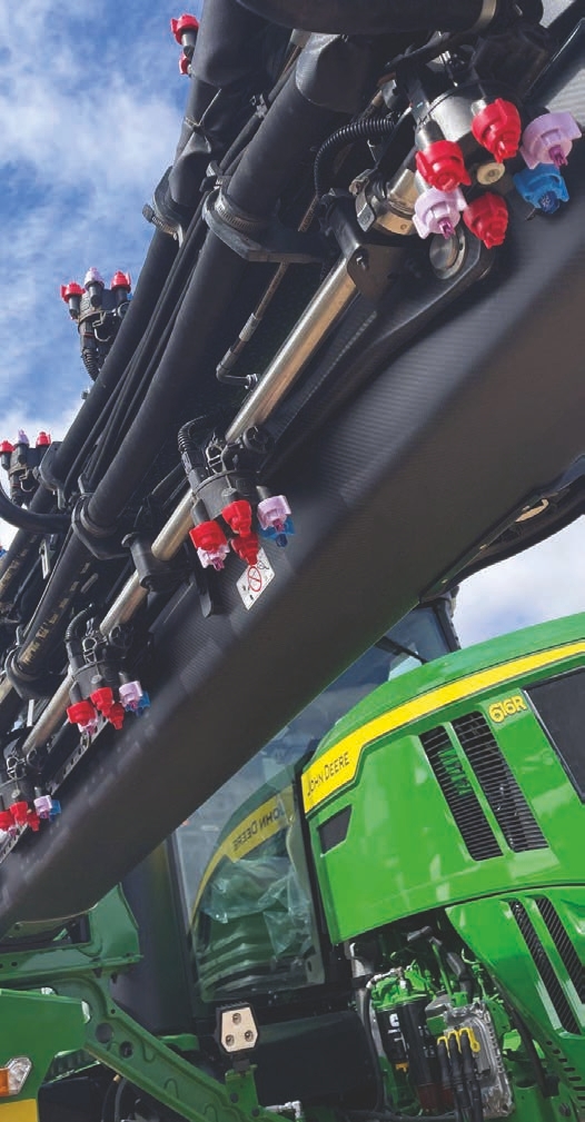
Nozzles are color-coded to reflect industry standards for flow rates (see page 42).
These hybrid nozzles provide the best of both worlds by using a tip that has an insert with a longer life. At the same time, they allow new innovations or design modifications to be incorporated into the plastic body, because it is relatively easier to mold plastics than other common materials. Using plastic also reduces manufacturing costs and allows manufacturers to color-code their nozzles, which can help growers save time in the field when switching from one nozzle to the next during spraying.
Here are some brief descriptions of the materials manufacturers commonly use to fabricate spray nozzles and tips.
Brass (BR, B, or VB)
Brass was the first metal used to manufacture nozzles. It is a soft metal that can easily be machined into nozzles. Brass nozzles work better under low pressures. The same “soft” characteristic makes it easy to machine brass nozzles also makes them susceptible to abrasive materials during spraying. As pressures increase, abrasive materials will enlarge the exit orifice and change the flow rate, fan angle, and droplet size. Generally, brass nozzles are not used in agriculture because of the higher pressures used and the abrasive pesticides applied. In addition, brass nozzles can be easily damaged when improperly cleaned. Furthermore, it becomes harder to read the nozzle size and spray angle information imprinted on the nozzle as they age.
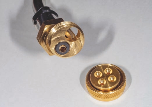
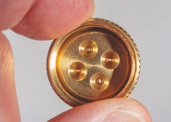
A brass nozzle like this one is commonly used by the pest control industry with manual pump-up sprayers. The nozzle shown here can be set to four positions depending on the desired spray pattern.
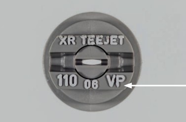
The VP printed on this nozzle indicates that the nozzle tip is made from a polymer (a.k.a. plastic). The V means the nozzle follows the ISO flow rate color-code.
Polymer nozzle tips have excellent wear resistance - they demonstrate less wear than stainless steel tips. Another advantage using polymer spray tips and bodies is the flexibility to make slight design changes. This allows the manufacturer to build specific characteristics into the nozzle on a very small scale. Manufacturers can tweak molds to add different designs, including internal chambers or air induction ports. Polymer materials created with an injection molding process can turn out many nozzles in a shorter time and save money. Instead of working with one nozzle at a time - like is done with stainless steel and brass - using polymers allows manufacturers to mass produce nozzles, which helps to reduce their costs.
Stainless Steel (SS, VS)
Stainless steel can withstand abrasive and corrosive materials. It also provides excellent wear life and offers more consistency in fan angle and droplet size distribution. The main problem with stainless steel nozzles is their cost. Manufacturers often insert stainless steel tips into polymer bodies to help reduce costs.

The VS or SS printed on this nozzle body indicates the insert is made of stainless steel.
Ceramic (VK)
Ceramic is a very hard material that is made from a quartz powder that contains a high percentage of aluminum oxide (alumina). The material is mixed with water and a binder, is placed in a mold, heated in an oven, and then cured. Ceramic tips, like most stainless-steel tips, are inserted into polymer nozzle bodies. Ceramic tips are the hardest and most durable tips on the market. They hold up well to corrosive and abrasive materials. However, some growers express concerns that ceramic is too fragile and could break if they are dropped on a hard surface like a concrete floor. Ceramic tips are widely used in hollow cone and disc and core nozzles used in tree fruit orchards and vineyards. Many of the fungicides applied to fruit trees are formulated as wettable powders and applied by air-assisted sprayers under high pressures. Ceramic nozzles perform well against abrasion. Some markets (like Europe and South America) have a greater interest in using ceramic nozzles on horizontal boom sprayers because of their durability.
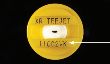
The VK printed on a nozzle indicates that it has a ceramic tip. The ceramic tip shown here is molded into a plastic nozzle body.
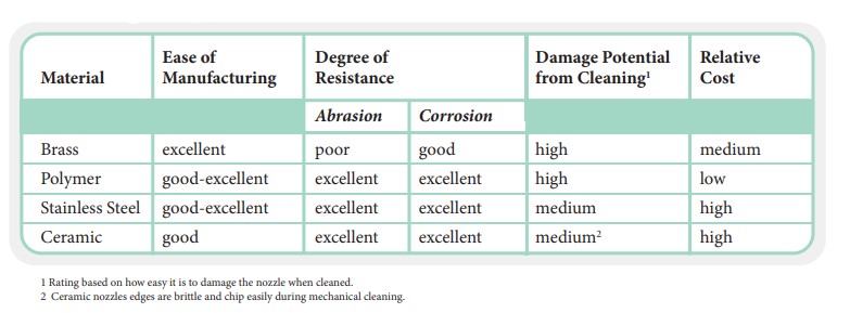
Nozzle Types in the Marketplace
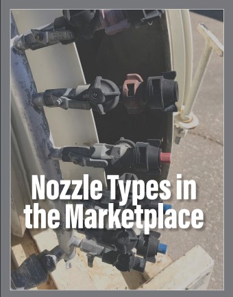
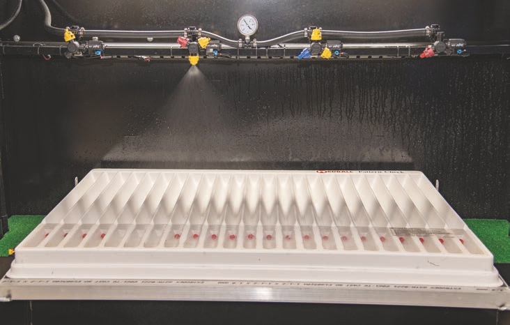
This photo shows a single swath from a tapered flat fan nozzle, which shows greater spray output in the middle compared with the ends of the pattern.
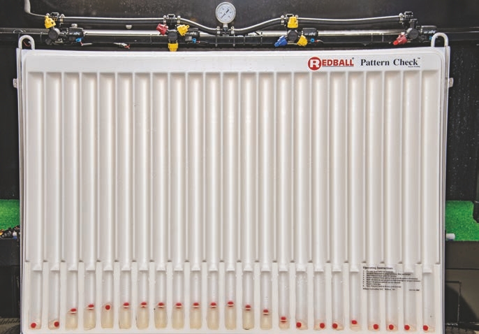
This photo shows the overlap between nozzle spray patterns that is required to compensate for tapered or reduced volumes along the outer edges of the spray pattern.
Historically, flat fan spray patterns were intended for horizontal booms. Applicators could adjust the nozzle spacing, boom height, and tapered volume of the spray to create an overlap that results in a uniform swath across the field. Specialty crops, such as vegetables, may use overlapping flat fans for broadcast applications, or banded applications where flat fans are arranged only over the row. In some cases, hollow cones, which have patterns that are intended to meet but not overlap, are still used on horizontal booms in specialty crops. Without some form of drift mitigation in these cases, the applications are very prone to off-target movement. Directed applications, such as hand wands or drop hoses, tend to employ flat fans or hollow cones, depending on the application.
Airblast (that is, orchard) sprayers, which employ air to direct spray to a three-dimensional canopy, often use hollow cones. With the increased use of wrap-around towers and vertical booms, airblast sprayers may also employ flat fan nozzles. The point is that there are always exceptions to how nozzles can be used to best apply the pesticide.
Nozzles that Primarily Fit on Spray Booms
Tapered Flat Fan Spray Pattern
Flat fan spray nozzles are the most commonly used nozzles in agriculture. As the name implies, these nozzles initially produce a two-dimensional, triangular spray pattern. In cross-section, the fan distributes more liquid in the middle and tapers toward each edge. In addition, spray droplet size distribution is not homogeneous at all locations within the fan. For these reasons, nozzles are never intended to be operated singularly or to deliver the liquid as spot spray applications.
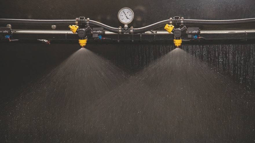
Properly overlapping tapered nozzles is important. The jets need to be offset 15° to avoid collision. Adjacent jets need to overlap but not collide.
To produce even distribution when using multiple nozzles on a boom, the neighboring nozzles must overlap. Furthermore, there are fewer, coarser droplets toward the edges of the boom compared to nozzles in the middle. An overlapping pattern not only makes the flow uniform, it also makes a more homogenous droplet spectrum. Broadcast tapered flat fan nozzles are mounted to a linear boom. they are popular because equipment fitted with booms can spray larger areas at faster speeds. Correctly overlapping the spray patterns of tapered spray nozzles will result in a uniform spray across the swath of the boom.
The proper overlap for 110° flat fan nozzles should be at least 50 percent. This will result in the sprays from adjacent nozzles intersecting each other at the midpoint of their sprays. Each nozzle on the boom delivers 50 percent of the target product to the spray area - the other half is delivered from the adjacent nozzles on its right and on its left. The resulting spray in the swath of the boom provides 100 percent coverage. Typically, this can be achieved at a 20-inch boom height for a boom with 20-inch nozzle spacing. Such spacing provides a very robust spray swath with maximum coverage and a low coefficient of variation. Keeping variation low is critical to avoid skips or streaks in the application and to maximize efficacy.
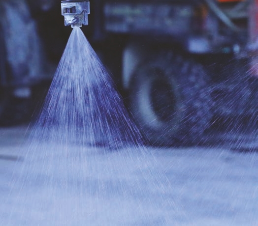
Adjacent nozzles overlap the spray pattern of one tapered flat fan nozzle.
Tapered that fan nozzles must be a certain height above the target to give the spray enough time for the pattern to develop after it leaves the exit orifice. Tapered flat fans are most commonly available in 80° and 110° spray angles, and normally can operate within a pressure range of 15 to 100 PSI, depending on the nozzle design. One advantage of tapered flat fan nozzles is that they are more forgiving (within limits) as the boom moves up and down, because the overlap prevents skips or streaks. We describe five types of flat fan nozzles below.
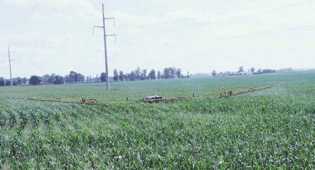
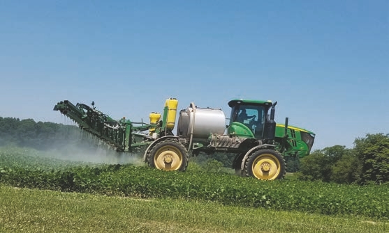
A tapered flat fan does not provide a uniform pattern if the boom is not level across the field. The lowest part of the boom can have gaps and the highest part may allow for spray drift.
One example of a tapered flat fan is called an extended range flat t fan (XR). Many nozzles have a minimum nozzle pressure they need to create the desired pattern. XR nozzles maintain a pattern at lower pressures compared to old flat fan nozzles. For example, it is common for a standard tapered flat fan nozzle to have an operating pressure range of 30 to 60 PSI, while the XR can produce a pattern when the pressure is as low as 15 PSI. XR flat fan nozzles work well with spray equipment outfitted with automated rate controllers. Spray patterns remain mostly the same over a considerable pressure range; however, changing pressures may alter droplet sizes (depending on the intensity of the pressure change). Spray solution characteristics (including, higher viscosity, lower surface tension, and so on) may also affect fan angle. Therefore, applicators must find the right combination of these parameters (along with boom height and nozzle spacing) to achieve a uniform spray application.
A second type of a tapered flat fan nozzle is called an off-center flat fan (OC). With these spray tips, the exit orifices are often wider to one side and are mounted at the ends of booms. OC nozzles essentially spray half a pattern toward one side (toward the center of the spray boom) instead of down the center like other tapered flat fan nozzles (see photographs below). It’s as if a tapered fan nozzle’s spray pattern is cut in half. The pattern starts off like an even nozzle on one side that would place the edge of the desired spray area (such as, fence row). Applicators should not use OC nozzles for broadcast applications across a field. They only should be used along field perimeters.
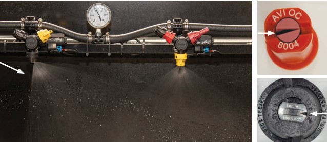
A third type of tapered flat fan nozzle is called a dual (or multi) flat fan. As the name suggests, these nozzles produce as one fan pattern that sprays into the sprayer’s travel direction (forward), while a second fan sprays at an angle away from the boom (backward). Manufacturers incorporated these designs into specific nozzles to improve both spray coverage and foliar canopy penetration. For example, spraying a fungicide on wheat heads or an herbicide on grassy weeds can be challenging, because they are vertical targets. Attacking the target at different angles increases the chance that the pesticide will contact the foliage and that the foliage will retain the pesticide. Some dual fan nozzles produce symmetrical fans that use the same angle (for example, 60°). In such cases, both spray patterns mirrored, and the spray angle is the same backward and forward. For example, the Turbo Twin Jet® (TTJ60) nozzle is symmetrical and has a 60°-angle between both sprays. Each spray is 30° backwards or forwards from the vertical, and each individual spray forms an 80º- or 110°-wide spray angle. Other dual spray nozzles are designed to produce asymmetrical angles (for example, 30° and 70°).
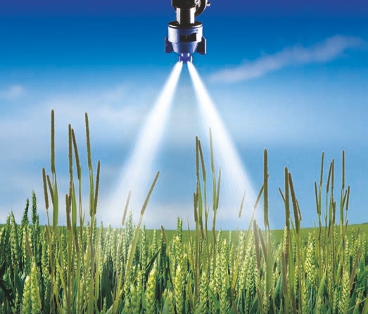
The two exit orifices on this nozzle create a symmetrical flat fan pattern with one spray directed forward and the other backward. The exit orifices are identical in terms of droplet size and flow rate.
For example, the TeeJet® AI3070 nozzle has a forward pattern of 30° to the perpendicular and backward pattern of 70° as well as a wider individual spray pattern than the forward pattern. This type of nozzle is ideal for fungicide applications because it provides superior coverage of all sides of cereal crop heads (such as wheat) at the top of the canopy. With these nozzles, operators may choose to alternate tips forward and backward along the boom to produce four different angles. There are also nozzle bodies that can accomplish the same thing by holding two flat fans of different angles. These nozzles may also come with pre-orifice for air-induction generating relatively coarser droplets in both fans. A fourth type of tapered flat fan is called a flooding nozzle or deflector flat fan. This type of nozzle is designed to deliver high volumes, especially when operators apply products directly to the soil (as with pre-emergence liquid fertilizer applications). Instead of the exit orifice defining the spray pattern, it is defined by a stream of fluid being pushed against a flat metal or polymer deflection plate.
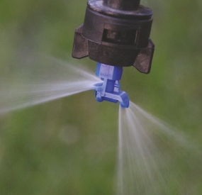
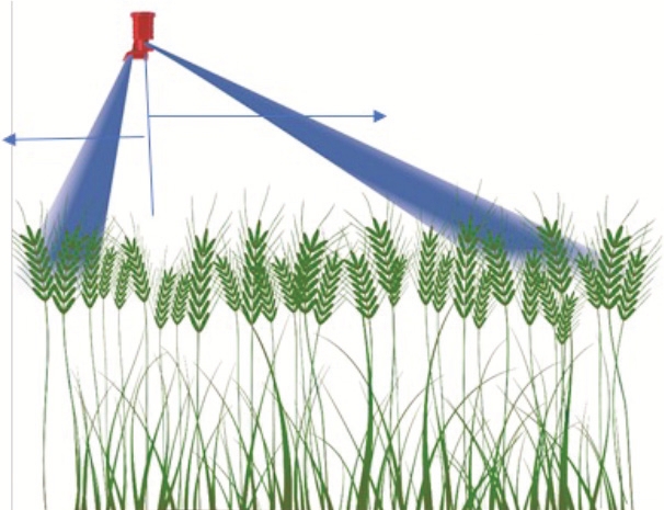
(Top) This asymmetrical A13070 TeeJet® nozzle shows two spray patterns. (Bottom) This diagram shows the two different spray patterns.
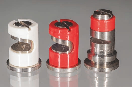
These high-volume nozzles have larger exit orifices that don’t clog easily. Usually, these nozzles do not provide a distribution along the boom as even as other that fan nozzles. However, new deflector-type flat fan spray tip designs produce larger droplets with a more uniform droplet size and a lower coefficient of variation.

A fifth type of tapered flat fan is called an even flat fan nozzle. The flow from even that fan nozzles does not taper toward the edge of the long axis of the fan pattern. These nozzles are generally used for banding applications over a specific area rather than broadcast. For instance, even nozzles may be suspended above planted rows when the pesticide may be too expensive to use as a broadcast application. Alternatively, applicators align even nozzles with the alleys and not the plant rows to apply herbicides to the weeds between rows of crops, not the crop.
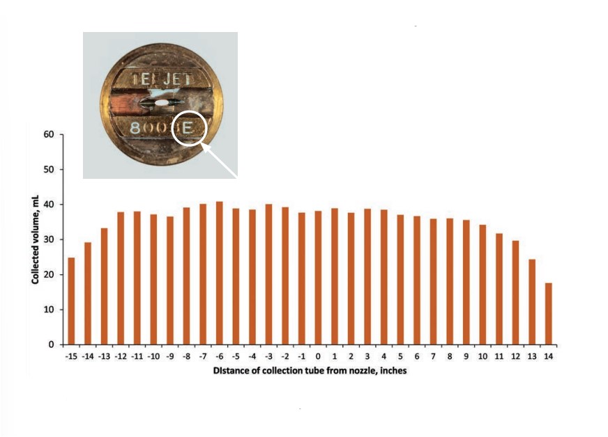
An even that fan nozzle is identified by the letter E in part of its description. The illustration shows an even pattern across the length of the spray width.
Even flat fan nozzles provide equal distribution over the entire spray swath without the need to overlap adjacent nozzles. Even flat fan nozzles are intended to be used individually. Any overlap between adjacent even nozzles would result in an overapplication of the spray solution. Using an even flat fan nozzle requires the operator to keep the height above the target rather precise. If the boom is too low above the target, then the pattern will be narrower than desired and result in an overapplication of the product (a smaller surface area will be covered with the same amount of product). If the boom is too high above the target, then the pattern will be wider than desired and result in an underapplication of the spray solution (a greater surface area will be covered with the same amount of product). Fortunately, nozzle manufacturer catalogs and websites provide the appropriate boom height for a given spray band width when using even flat fan nozzles.
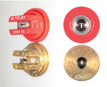
These photos look into the nozzles toward the exit orifices of a conventional tapered flat fan (top, red stainless-steel nozzle) and an even flat fan (bottom, brass nozzle). Notice the differences in the shape of the exit orifices and the width of the cuts of the tapered flat fan (red nozzle) and the even flat fan (brass).
Other Hydraulic Nozzles
Nozzles in this “other” category include cone, solid stream, and boomless nozzles. Some boomless equipment may come with rotary atomizers which are present on some new drone application units. However, this publication will not discuss rotary atomizers.
Cone Nozzles
Cone nozzles can be divided into two types: nozzles that produce a hollow cone pattern and nozzles that produce a full cone pattern, which can be produced mostly by swirling the liquid. Cone nozzles may be offered in a single-piece design or in a two-piece disc and core design. Cone nozzles are used mostly for insecticide and fungicide applications to field and fruit crops when foliage penetration and complete coverage of the lower leaf surface is critical for effective application. The major difference between the two is that with the hollow cone, most of the spray droplets are concentrated at the edges of the cone. With the full cone, the spray droplets are spread somewhat uniformly across the cone pattern. The cone angles for nozzles may vary between 30° and 170°. Operators can control the flow rates for both nozzles by selecting orifice/disc inserts of different sizes or volume capabilities. For a disc insert, the full cone disc presents a slot in the middle (as shown in the illustration on page 63). Manufacturers developed a newer type of hollow cone nozzle with an air-induction system for use in airblast sprayers when applicators need drift control. Some applicators can use the combination at the bottom part of an airblast regular hollow cone nozzle and at the top air-induction hollow cone. These nozzles were designed to work separately from one another. However, some applicators use them on horizontal linear booms. When they do that the distribution across the boom shows a lot of variability with the coefficient of variation of 20 percent or more.
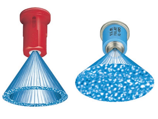
This illustration shows a hollow cone (left) and full cone (right). The illustration of the hollow cone shows spray droplets concentrated at the edges of the cone; however, this is somewhat misleading. As the droplets are dispersed along the circular pattern, many small droplets are propelled into the center of the nozzle.
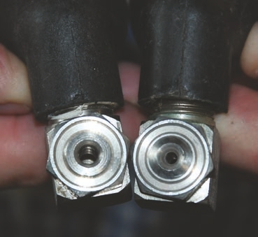
These photos show examples of hollow cone nozzles (top), which show the larger exit orifices to allow high-volume applications. The nozzle with the larger opening can apply 2.5 gallons of water per minute, while the smaller exit orifice can apply 1.25 gallons (bottom).
Solid Stream Spray Pattern
As the name implies, solid stream nozzles produce a liquid stream. Some solid stream nozzles have multiple exit orifices to help distribute the product. There are a variety of sizes that can include one to seven individual streams.
This nozzle forms a solid stream for applications that do not require atomization of spray liquid (or when atomization is not desirable) for an effective application, such as liquid fertilizer applications on wheat after emergence. A spray cloud of droplets would effectively cover the wheat foliage and result in leaf burn. The solid stream design avoids thorough leaf coverage and results in minimal leaf injury.
For instance, applicators use one-stream jet nozzles to apply fertilizers, insecticides, and biologicals directly into the furrow close to the planted seed. Three-stream (or similar) tips produce a narrower coverage area and project liquid more directly onto the soil surface. Users commonly use such nozzles for directed spray applications. Seven-stream tips produce a wider coverage area, which makes them ideal for broadcast applications in both standing crops and bare soil. Due to the greater number of streams and wider spray pattern, these tips are ideal for higher boom heights and higher ground speeds.
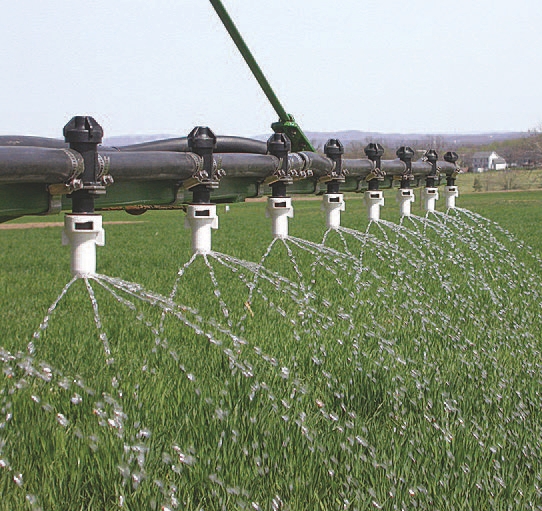
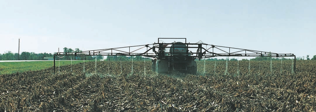
Boomless Nozzles
Boomless nozzles deliver uniform spray patterns across broad areas where application with a boom sprayer would be difficult — the boom could hit obstructions (such as brush), or the terrain is so uneven that the boom height would be too variable. An applicator might mount a single boomless nozzle on the back of an ATV. This would be easier than using a 10-foot-wide fixed boom for herbicide applications in pastures and golf courses.
These photos show boomless nozzles in various applications:
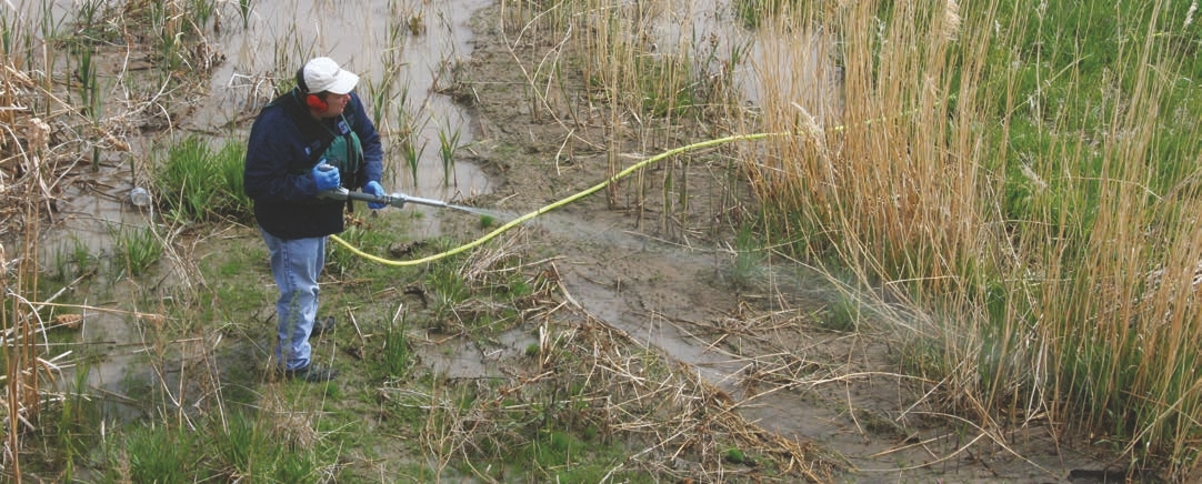
(A) to control invasive weeds in rights-of-way,
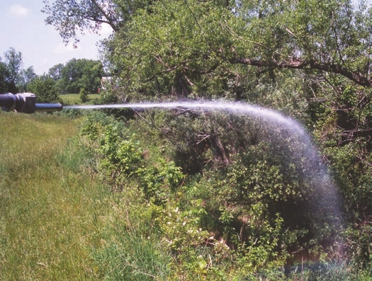
(B) to control brush in a ditch bank, and
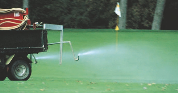
(C) to make a golf course application.
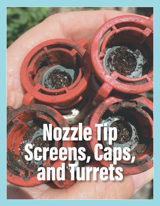
Nozzle Tip Screens, Caps, and Turrets
Screens and caps are accessories that play important roles in the pesticide application process.
Screens Help Prevent Nozzle Plugging
Applicators often use water from local sources that contain solid particles and debris, especially for rights- of-way applications. When the applicators place screens (that is, filters and strainers) before the nozzles’ exit orifices, it can help remove those suspended materials in the liquid stream that could plug up the exit orifices. Line strainers and tip strainers are very important to the systems and must be properly sized and placed and be in good condition. Such preparations can help prevent spray tips from clogging and assure the tank mixture is properly filtrated. Applicators can select nozzle screens by the nozzle sizes and the types of products (herbicides, fungicides, etc.) they are applying. Properly sized screens can remove solid objects (like grains of sand) found in mixing water. They can also capture undissolved solid pesticides that were inadequately agitated in the spray tank. Screens can extend nozzle life by capturing these abrasive materials before they pass through the orifices.
There are several common mesh size ratings for nozzle screens used in pesticide applications: 50, 80, 100, and 200 mesh. A 50-mesh screen has 50 openings per linear inch, an 80-mesh screen has 80 openings per linear inch, a 100-mesh screen has 100 openings per linear inch, and a 200-mesh screen has 200 openings per linear inch.The screen openings get much smaller the more openings it has. The openings on a 100-mesh screen are 150 microns, while the openings on a 50-mesh screen are 300 microns. This means that 100-mesh screens capture and retain smaller solid particles before the spray liquid enters the nozzle.
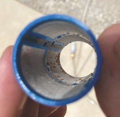
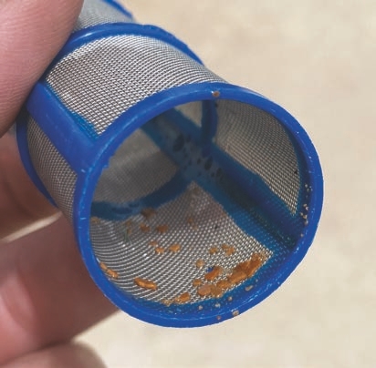
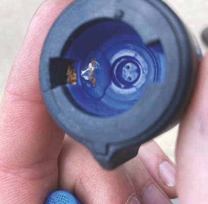
These photos show inline strainers filtering particulate matter in well water. The photo with the nozzle body shows what the nozzle body strainer (screen) filtered out so that the Greenleaf tip would not plug or have the spray pattern compromised by the particulate.
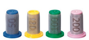
Screens are color-coded to help identify mesh sizes. More recently manufactured screens are also marked their mesh size for quicker identification. This photo shows that a blue 50-mesh screen, a yellow 80-mesh screen, a green 100-mesh screen, and a pink 200-mesh screen.
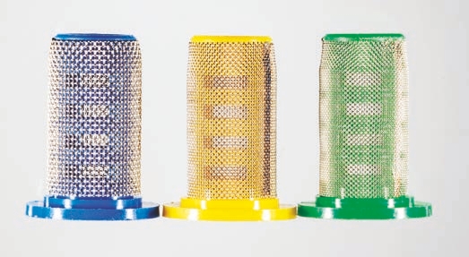
A screen’s width determines what size materials will pass through it. The blue 50-mesh screen has larger openings than the yellow 80-mesh screen, which has larger openings than the green 100-mesh screen.
Manufacturers determine screen size recommendations by considering the preorifice nozzle flow rate and exit orifice size. Nozzles with lower flow rates have smaller screen sizes (higher mesh numbers) while higher flow rates have larger screen sizes (lower mesh numbers).
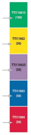
For example, a nozzle with a low flow rate of less than 0.2 gallons per minute (GPM) will generally be paired with a 100-mesh screen. The lower flow rate means the nozzles have smaller pre- and exit orifice sizes, which means they are easier to plug. Nozzles with flow rates at 0.2 GPM or greater have 50- or 80-mesh screens. Such screens are recommended because smaller particles can pass through the exit orifices. Dual nozzles can use different screen sizes because each exit orifice is half the size of a single fan nozzle with the same flow rate.
COLOR-CODES ARE NOT LINKED
It is important to note that the color assigned to screen mesh size, nozzle flow rates, and spray droplet size categories are independent of one another. Each one follows a different ISO standard that determines the color coding.
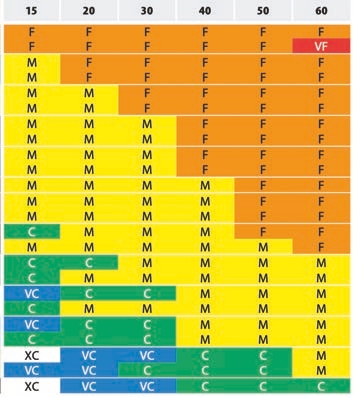
(A) This chart shows the color coding for droplet sizes.
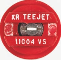
(B) This red nozzle specifies a specific flow rate.
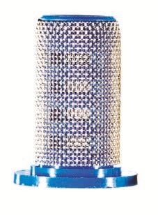
(C) This blue screen indicates a specific mesh size. This standardization allows manufacturers to more easily evaluate nozzles and screens.
Nozzle tip screens do not alter the flow rate until the screen becomes clogged with debris. Problems with clogging exit orifices often arise when operators use finer mesh screens (such as 100-mesh) rather than a screen the nozzle manufacturers recommend (such as 50- or 80-mesh).
For example, a general recommendation for applying complex pesticide formulations (such as a suspension concentrate, capsule suspension, etc.) is a 50-mesh or coarser screen. If an applicator uses a finer screen (such as 100-mesh), the screen can get clogged and slow the flow rate. If applicators use these finer, larger-numbered screens, they may have to clean them more often, meaning down time in the field.
To avoid excessive clogging, it is also important to correctly select the screens for the line strainers. Self- cleaning line strainers minimize clogging but do require minimum flow rates - 6 gallons per minute for ¾- and 1-inch sizes, 8 gallons per minute for 1 ¼ and 1 ½-inch sizes through the bypass line. Operators also should make sure the tank mixture is prepared according to the manufacturer’s recommendations to avoid incompatibility.
Opinions differ on whether screens at the spray tips are necessary. Some commercial application companies no longer use tip screens ahead of the nozzles. Instead, they have reduced the mesh sizes of the screens on the inline filters before and after the pump. They save time by not having to clean so many screens — 96 screens on a 120-foot boom placed on 15-inch centers.
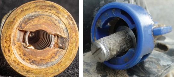
(Left) This stainless-steel screen uses a spring ball-valve to reduce dripping out of the nozzle. This is important if a nozzle body doesn’t have a rubber diaphragm valve above the tip as shown in the photo on the right. As a general rule, do not combine a spring ball valve screen with a nozzle body that has a diaphragm valve.
WARNING! NOZZLE SCREEN COLORS CHANGED
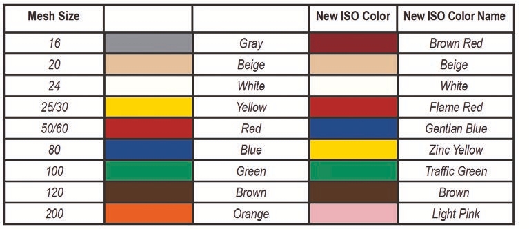
Since screens do not wear out as quickly as spray tips, applicators may have screens they purchased more than 10 years ago. Using screens purchased before 2016 is problematic because the ISO changed the colors assigned to screen mesh sizes that year. Be wary of screens that do not have the number marked on them. You could unintentionally mismatch the wrong screen with a nozzle. While today’s green screen is the same mesh size as the pre-2016 screen, the old red and blue screens changed. Colored-coded screens that do not have numbers are signs of older screens. Use the chart to properly size your unnumbered screens.
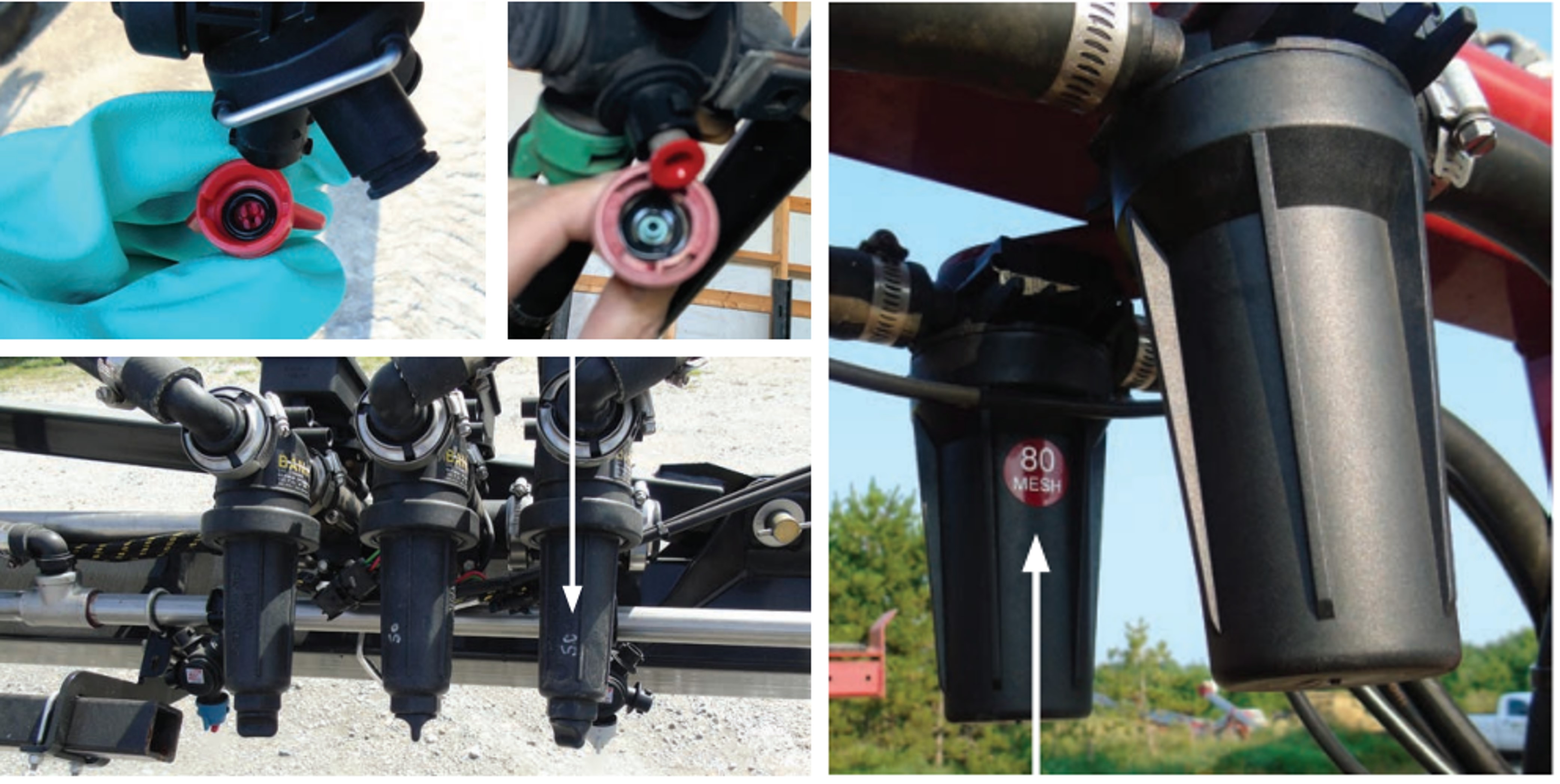
Screens can be used for inline filters for each boom section, in each nozzle body, or both. Applicators with large commercial booms that have numerous nozzle bodies and up to five spray tips on each nozzle body try to avoid using screens in each spray tip cap. This reduces the number of parts they need to clean and inspect.
Spray Boom, Turrets, and Caps
There are generally two categories of booms: wet or dry. The categories are based on how the liquid is supplied to the nozzle body. A wet boom has a standard stainless-steel or plastic pipe, and the nozzle bodies are attached directly into the boom. A dry boom has a steel, aluminum, or carbon fiber boom structure with rubber hoses (for example, EPDM) that connect individual nozzle bodies, which are mounted on the boom structure (see photos below). They are called dry booms because no liquid flows through the boom itself.
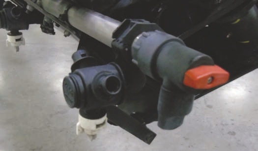
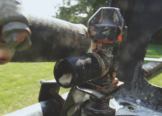
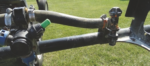
Different cap designs hold and lock specific nozzles in place.
Wet booms come with pre-drilled holes (for example, 15 inches apart) where applicators will mount the nozzle bodies. If an applicator wants 30-inch centers, they can shut off every other nozzle.
This 90-foot wet boom has 15-inch centers, which means there are 72 evenly spaced holes in which to place the nozzle bodies.
One popular adaptation for wet and dry booms is a nozzle turret, which provides an attachment point for multiple nozzles. Turrets can be made to hold three to six nozzle caps.
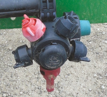
By twisting the turret, applicators can quickly switch nozzles when crops or environmental conditions change.
Nozzle turrets that have multiple nozzles attached allow applicators to select the proper spray tip to deal with different scenarios. They may select the right nozzle to help them manage drift, provide a greater application volume, or generate a finer droplet spectrum for greater spray coverage. Because turrets make it is easy to switch from one nozzle to another, applicators can change spray tips quickly to optimize each application.
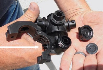
The stem on this new turret (arrow) fits into the hole in a wet boom, which is then clamped in place.
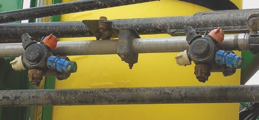
When installing nozzle tips on turrets, make sure to place each tip in the same order on each turret. This will speed the transition to a new nozzle and reduce any chance for error in selecting the wrong nozzles.
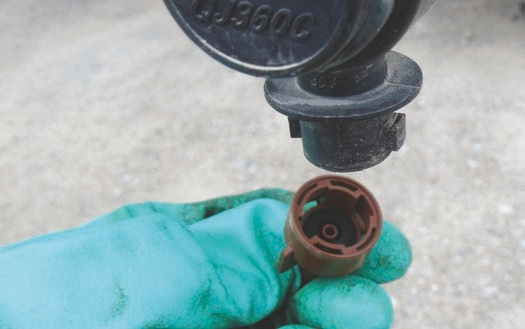
This photo shows a cap with a built-in plastic tip before being placed on the turret.
Spray caps hold the nozzles and (if used) filter screens. Caps are specifically shaped parts that hold nozzles in place, attach the nozzles to the nozzle bodies, and ensure proper seals to prevent any leaks. Manufactures have created spray caps of numerous designs as nozzle types, equipment booms, and other application equipment have changed over time. More caps are specifically designed for different spray nozzles to fit in. This means nozzles are made to fit into certain of caps, which are then attached to certain boom components. There are a few standards that designate the dimension of spray bodies. There are differences, but spray bodies from different manufacturers are more similar than dissimilar when it comes to external dimensions. Nozzles must be designed to adapt to the bodies that applicators commonly use.
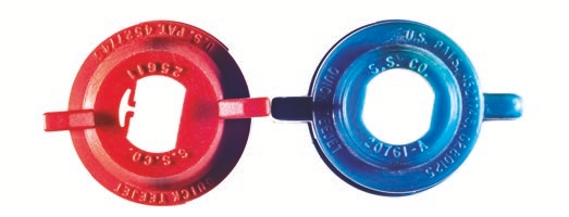
Different cap designs hold and lock specific nozzles in place.
It is important to realize that a cap’s color is independent of the color of the nozzle inserted into it. Manufacturers color their caps for applicators who want to match the cap color to the nozzle flow rate color.
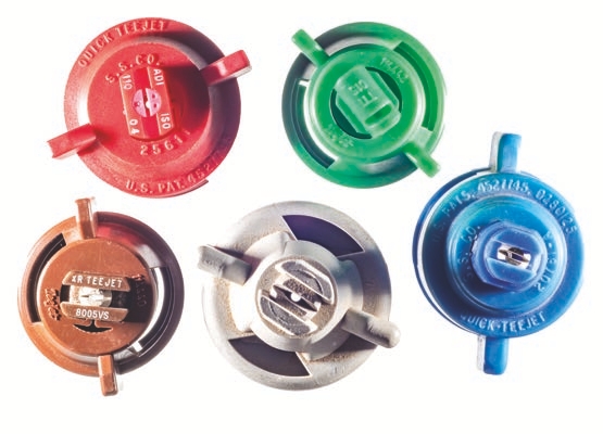
This photo shows quarter-turn spray caps color-matched to appropriate spray tips.
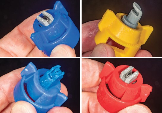
Spray nozzle caps firmly fasten spray tips to nozzle bodies and orient spray patterns correctly along booms. During the busy spray season, operators must quickly decide which nozzle to select. Colored caps that match colored nozzles can help applicators see that all nozzles on a boom are the same and help eliminate mistakes. However, you can still use the cap and tip even if you are not matching the color cap to the same-colored nozzle.
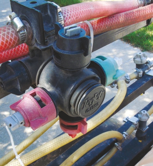
This photo shows different colored caps with different colored nozzles. In this case, the colored caps are randomly used to attach the nozzles to the boom. Color caps offer no visual advantages over standard black caps when used in this manner.
There are a couple of reasons why one should use colored caps to match the colors of the nozzles being used. The first reason is that many stainless steel and polymer spray tips are difficult to read once they are on a sprayer. By using caps with a color similar to the nozzles, applicators can quickly ascertain the flow rates of each nozzle. A second reason to match the colors of the caps and nozzles is to be able to more easily see the colors when the spray equipment gets dirty.
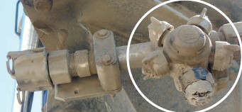
Many nozzles are available where the nozzle tips and caps are molded into one unit. Two examples are the TeeJet® AIC and XRC. The C in the name indicates combination/combo. When combo nozzle tips and caps are available and meet your needs, this is usually the best way to purchase the nozzle tips and caps for easy assembly.
Demystifying the Nozzle Selection Process
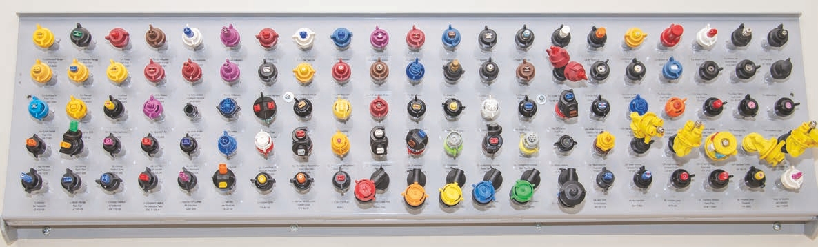
Nozzle choices are nearly limitless. It all depends on what you need to find the nozzle that will provide the best results.
Spray nozzles have evolved from the more simplistic designs of yesteryear to more complicated and diverse designs. With improved manufacturing and engineering processes, modern nozzles can operate reliably over greater pressure ranges and produce consistent droplet sizes and spray patterns for a wide range of flow rates.
With literally hundreds of designs available, selecting the nozzle best suited to your task can seem daunting. It’s easy to feel overwhelmed when confronted with the technical language and seemingly complicated, multi-colored tables filled with numbers. The problem gets worse if you go straight to the catalogs if you haven’t considered what you want those nozzles to accomplish. The good news is that, with a little upfront effort, you will soon be an expert at reading and interpreting the information from nozzle manufacturers’ tables and charts.
The consequence of choosing the “wrong” nozzle is to compromise the spray job. This might mean wasting product; failing to control pests; increasing the potential for resistance; or creating off-target situations that can damage the environment, residential areas, and other agricultural operations.
In each case of selecting an improper nozzle, there is an economic reckoning. Consequences include:
• The cost of using too much pesticide
• The cost of fuel
• The cost of lost yield
• The future cost of dealing with resistant pests
• The cost of drift or run-off remediation (which might include buying an expensive specialty crop and the risk of being dropped by your insurance company)
• The time you will spend dealing with one or more of these issues
So, investing a relatively small amount of time to understand the science behind nozzles will help you make a more appropriate choice that will pay dividends. Still, there will always be a segment of growers who prefer to rely on the nozzle recommendations of retailers, salespeople, consultants, or fellow farmers in the neighborhood. This faithful approach assumes that your advisor isn’t “selling something” and that they have done the legwork required to understand the best nozzle choice for your unique situation. Wouldn’t it be prudent to have a working understanding of how to choose a nozzle, if only so you can ask them a few important questions to keep them “honest”? Perhaps you feel that replacing a worn set of nozzles with exact replicas is the fastest and safest approach. This decision centers on the belief that if those worn nozzles performed well in the past, then it is logical to assume they will continue to perform well in the future.
Buying that exact set of nozzles that has worked for you in the past may be fine, but you want to make sure that these application parameters have not changed:
• You are spraying the same pests
• You are operating the same sprayer
• You are applying the same products or similar chemistries
• You are applying the same volume (GPA)
• You are using the same speeds and pressures
• You are spraying under the same weather conditions
• You have noted that everything bordering the field remained the same
• You are operating under the same regulatory requirements
If all these factors remain the same, there is no harm in saying, “I’ll take another set of these same nozzles, please.” But even if your situation has remained the same, there still may be new nozzle designs that offer better performance. You may not be taking full advantage of new designs and technology that can reduce the range of droplet sizes. Fewer droplets from the largest part of the spectrum reduce run-off and waste. Fewer droplets from the smallest part of the spectrum reduce the potential for off-target drift. This leaves you in the Goldilocks zone of efficient and optimal control.
WHAT YOU HATE TO SEE
One crop consultant tells the story about the problems improper nozzle choices can create. “I recently went to a field complaint where the applicator claimed the lack of control was due to weed resistance. The grower had used an air induction nozzle to apply a post-emergent contact herbicide. “The manufacturer’s catalog clearly indicated that this nozzle design was not appropriate for contact herbicides. So, the true culprit was not resistance; it was poor coverage that resulted from droplet sizes that were too large. There was nothing else I could say to make the situation any better.”
Altering One Variable Changes All Others
Replacing worn-out nozzles is an opportunity to evaluate whether the current nozzles are still the best option. There are general rules of thumb to remember when purchasing new nozzles, including:
• Nozzle spacing and spray fan angle
• Amount of spray carrier
• Travel speed
Nozzle Spacing and Spray Fan Angle
Nozzle spacing and the spray fan angle (as influenced by nozzle design and pressure) determine the optimal boom height. Nozzle spacing and boom height collectively determine the degree of spray overlap. Excessive overlap isn’t a problem, but additional nozzles do mean added expense, cleaning time, and potential for plugging. The closer the nozzle spacing, the more nozzles there are on the boom, and the smaller each nozzle must be to account for GPM output per nozzle. This could mean more potential driftable fines as the nozzle spacing decreases. An operator could negate this slight change in driftable fines by using a lower boom height. Conversely, gaps in the pattern from relatively widely spaced nozzles and low boom height could lead to sub-lethal applications or that-out misses. Some nozzles have an attack angle of 15°. This permits a lower boom height and improves the spray pattern over straight down.
Nozzle manufacturers generally recommend a 100 percent spray overlap for that fans. This creates sufficient overlap when the boom sways low to the ground. It also increases the degree to which droplet sizes are homogeneous under the boom, because coarser and fewer droplets are generally found at the edges of the pattern compared to the center. To ensure this degree of overlap, operators should observe and consider changes in fan angle over their typical pressure range.
Be aware: Some nozzles don’t produce the fan angle they advertise. It’s always prudent to visually inspect sprayers during calibration to ensure sufficient overlap. Make sure to use water in the calibration and not the pesticide solution. Use gloves even though it is only water in the tank. Although it will be hard to calculate the exact overlap in the field, you can have a great idea. To check the spray pattern, use an LED strobe light in dark or low-light conditions to more easily determine the spray pattern and droplet size.
Amount of Spray Carrier
Use the amount of spray carrier necessary to achieve spray coverage. This improves the odds of achieving threshold coverage. Nozzles that emit a higher flow rate tend to produce fewer fines than the same design with a lower flow rate.
Travel Speed
Travel speed can influence boom height. As a sprayer’s travel speed increases, the boom height can fluctuate more based on field topography changes, or the boom can bounce over uneven field surfaces. Manual or automatic boom height corrections will not be as responsive at faster speeds. As the speed increases, boom height usually varies more. If you can maintain the boom height as the sprayer speed increases, then there should not necessarily be more drift. To avoid problems, drive as slow as is economically feasible to maintain a stable boom height and allow for coverage across the field or treated area. Typically, sprayer travel speeds for perimeter application passes around fields are slow to maintain minimal boom height and low spray pressure to allow operators to reduce physical spray drift and watch for spray obstacles or sensitive areas along field edges.
Many people still believe nozzle choice is solely a matter of droplet size, carrier volume, travel speed, and pressure. Those are all critical selection criteria, but what is more important is how these factors interact with each other. Altering one spray variable will affect the other variables. Assume you are having trouble controlling white mold in soybean with a nozzle that generates a volume median diameter (VMD) in the very coarse category. The retailer asks what carrier volume you use? You answer, “Ten gallons per acre.” The retailer follows up with his first question asking if can you bump your rate to 15- or 20-gallons per acre? You reply, “I can make 15 gallons work, but 20 gallons would slow me down too much.”
“Can you slow down a little?” the retailer asks. “Pick a speed that allows you to get the job done in a reasonable time. At these faster speeds you are traveling, the booms are higher.” The retailer asks one last question, “Is there anything around you that you who would be worried about off-target spray drift?” If the answer is yes, then a medium VMD nozzle usually works well for reducing spray drift while still providing the satisfactory spray coverage needed for contact-type pesticides. You are lucky that the nozzle being used was versatile enough to make those changes without having to purchase a new set. In a perfect world, the best application for the above example would be achieved by using more water, driving at slower speeds, having nozzles that produce smaller droplets, and lowering the booms to improve spray movement into the canopy. But is there ever a time that’s perfect for spraying? Many of the questions that determine how the sprayer is calibrated and pesticides are applied properly rely on the applicator’s knowledge and management skills. Without additional information and modifications, the charts nozzle manufacturers provide are only one piece of the whole application puzzle.
The charts provide the technical parameters. In other words, if you do this, then this will happen. But you still must decide the nozzle type, droplet size, application speed, and carrier volume by considering different factors. For example, those factors can easily be changed by knowing what is around the property being treated - such as ponds, lakes, streams, sensitive crops, and beehives. You must know the context of your application before you can pick a nozzle specific to that pesticide, specific to that crop, and specific for the targeted site.
Criteria for Selecting New Nozzles
As we have established, no single nozzle can do it all. You’ll need a few nozzles to handle common situations, weather changes, and specialty applications. There are many ways to select a nozzle for each situation, but we propose these ten criteria.
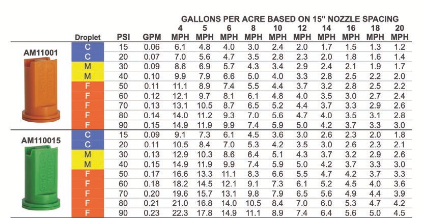
Nozzle manufacturers publish tables that list the critical calibration factors: nozzle spacing; gallons per acre; travel speed; droplet size; nozzle flow rate; pressure; and in some cases, initial spray angle. Using Greenleaf Technology’s AirMix® nozzle as an example, you can see that these factors are interrelated — changing one affects the others. You need to know how your sprayer operates before looking at such tables.
Criterion 1: Droplet Size
Some pesticide labels prescribe droplet sizes, others do not. For example, one herbicide label says to use “nozzles and pressures that generate Medium (about 250 to 300 microns) spray droplets as reported by the nozzle manufacturer and in accordance with ISO 25358. Do not use nozzles and pressures that result in Coarse sprays. Fine sprays should also be avoided to minimize spray drift risk.”
When you search a nozzle table for a spray droplet, it’s best to focus on the classification symbols (VF, F, M, C, VC, XC, UC). There are colors associated with droplet size, but they are easily confused with the colors associated with flow rate. In the following XR TeeJet® table, you’ll see that a medium (M) nozzle also has a “yellow” color code. However, yellow can also denote an 0.2 (XR8002 and XR 11002), which is a nozzle that emits 0.2 GPM at 40 PSI. In other words, a nozzle constructed of yellow plastic does not mean it creates a medium droplet size.
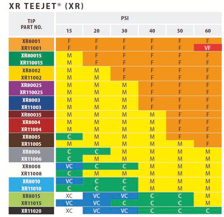
Looking at the XR that fan nozzle in the TeeJet® catalog, we find that a medium droplet size is influenced by pressure and the orifice size that dictates flow rate (gallons per minute per nozzle). This table clearly shows that changing the orifice size and pressure can change the droplet size category from fine (orange), to medium (yellow), to coarse (green), to very coarse (blue), to extremely coarse (white). Based on the herbicide label requirements, an operator could produce a medium spray droplet by utilizing several different nozzles with different orifice sizes (or flow rates) at different pressures. But if you compare the driftable fines of an XR with those of a Turbo TeeJet® (TT), you will see that both produce a similar droplet size range; however, the TT nozzle produces far fewer driftable fines than the XR, which means the TT provides a lower risk of spray drift for herbicide applications.
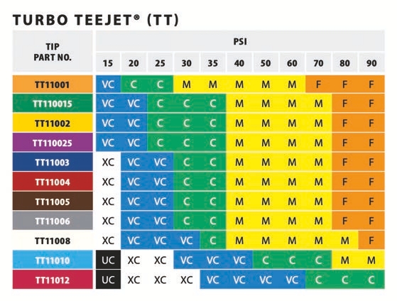
When pesticide labels are silent on preferred droplet sizes, you will need to use your judgment when selecting nozzles. This means you need to know if the product is contact spray or if it is a systemic product. Whether the product is a contact or systemic pesticide will influence the droplet size you desire and the nozzle you select. Research shows that larger droplets better penetrate the canopy because they maintain velocity, while smaller droplets lose momentum and fail to penetrate the canopy as well.
Contact products tend to require smaller droplets, because they increase the odds of hitting (and being retained) smaller and hard-to-wet targets and cover more out-of-sight surfaces. Finally, the finer the spray, the more droplets there are for a given volume, which has the potential to increase deposit density and improve the odds of contacting targets that may have diseases and some insects.
But, as we have established, it is hard to control the fate of small droplets. They are more prone to drift, and this can compromise coverage uniformity. Large droplets have a greater chance of penetrating the canopy. The question becomes how much coverage we need in the canopy because large droplets don’t provide adequate coverage.
Systemic (translocated) pesticides do not require thorough coverage on target surfaces, which may permit the use of coarser droplets. Coarser droplets are less prone to evaporate and to move off-target by wind or turbulence. Once coarser droplets deposit on a surface, they may remain in liquid form longer than finer deposits, and this can improve the chances of pesticide’s active ingredients to penetrate the target tissue.
Unfortunately, current nozzles do not provide uniform droplet sizes. For this reason, nozzles will always discharge unwanted droplets. For example, we know that soil-active herbicides are relatively insensitive to droplet size, so it would make sense to use coarser droplets to ensure they stay on target. On the other hand, crop residues left in the field may prevent coarser sprays from reaching the target, so finer droplets would improve coverage. Fortunately, medium-coarse spray classifications would have enough variability and range of droplet sizes to give us the best of both worlds.
Herbicides are generally more forgiving than fungicides and insecticides when it comes to coverage, because many herbicides have systemic activity in the target weeds. That means a droplet need only contact some part of the target weed for the active ingredient to physically penetrate the tissue.
For such uses, you can use a coarse spray or carrier (with sufficient volume) without the risk of missing the target. Additionally, coarser droplets form deposits that remain in liquid form longer than finer droplets, which provides more time for the active ingredient to penetrate the plant.
Fungicides are often formulated to work as protectants on leaf surfaces. Many diseases infect leaves as airborne spores. That means fungicides must already be in place and spread evenly over the leaf to ensure the spore contacts the fungicide residue. To improve the odds of contact fungicide-to-spore contact, the fungicide may be best applied as fine and medium spray droplets.
Insecticides also tend to be formulated as contact products, but spray coverage may not be as crucial as with contact fungicides. That is because many insects are mobile and there are better odds that they will walk on or eat the product. A medium-coarse spray droplet may be sufficient for threshold coverage.
½ = 8
Consider the volume of liquid in a 500 ›m diameter droplet. Now consider the volume in a droplet half that diameter: 250 ›m.
You might think that by cutting the diameter in half, you get twice as many droplets, but you’d be wrong. Volume is cubic, so there is enough volume in a single 500 ›m droplet to make eight 250 ›m droplets! So, there are really two ways to improve the odds of achieving good coverage:
1. Raise the carrier volume applied per acre
2. Reduce the average droplet size
Criterion 2: Carrier Volume
The general convention is that more water translates to better coverage. That is true up to a point, but there’s a diminishing return as sprays saturate surfaces and the product simply runs off. A conventional hydraulic nozzle meters the flow of bulk spray liquid, converts it into a range of droplet sizes, and disperses them in a specific geometric shape. This means operators performing a broadcast spray can control carrier application volume in four ways.
They can:
1. Alter travel speeds
2. Change pressures
3. Choose a nozzle with a different flow rate
4. Shut off every other nozzle with the nozzle spacing (for example, on 10-inch or 15-inch spacing)
Labels often list the minimal carrier volume. An instruction from one insecticide label provides the following details: “Use a minimum of 5 to 10 gallons per acre, increasing volume with crop size and/or pest pressure.” The maximum carrier application rate you can use will depend on your schedule, of course (refills take time). But as the label indicates, the size and density of the crop and the degree of pest densities you are dealing with should be the primary considerations when choosing carrier volume.
Criterion 3: Travel Speed
Travel speed often involves making a compromise between timely applications and precise applications. If you find you’re always rushed and that you abandon best practices just to “get it done,” then you should step back and look critically at your spraying strategy. What is the bottleneck? How can you address it?
In any application, it is nearly impossible to maintain a constant speed from start to finish — at a minimum, you must slow down to navigate end row turns. The faster you drive your spray, the more the rate controller will increase spray pressure to achieve the desired carrier volume. As pressure increases, droplet size distribution will change.
For example, an XR11004 nozzle identified as producing an average medium droplet spray (yellow color-coded in the table on page 78) at 15 PSI could generate fine spray (orange color-coded in table on page 78) in the pressure range starting at 50 PSI.
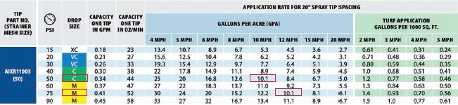
On the table above, we can see that when applying 10.1 GPA at a speed of 10 MPH at 40 PSI, the AIXR11003 tip will produce a coarse spray. But if the speed is increased to 12 MPH, the pressure also increases to 60 PSI, and the nozzle will now produce a medium spray.
As we’ve discussed, faster travel speeds carry the potential challenges of higher or bouncing booms. This is a function of the boom linkage design. Even with auto-leveling systems, this can still be a concern. High or changeable boom heights increase drift potential and produce less uniform deposition under the boom.
THE POOR HUMBLE NOZZLE
Everyone wants the perfect droplet size — large enough to stay on course and defy evaporation, but small enough to increase droplet counts and improve coverage and retention. Fortunately, we can hedge our bets a little when we consider that each nozzle produces a range of droplet sizes. Ultimately, the humble nozzle can only do so much. While it represents the last point of control for a sprayer operator, it is still only a part of the overall spray strategy. So, it is not only the tool you use, but how you use it.
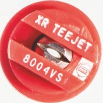
Criterion 4: Nozzle Angle
The key to effective application is to get as close to 100 percent uniformity in volume distribution across the boom as possible. This simply means that whatever is below the nozzles is going to get the same rate and the same combination of droplets. This consistency always improves performance.
Twenty years ago, 80° nozzles were the standard that fan angle choice. The spray pattern for an 80° that fan nozzle, like all that fan nozzles, tends to have large droplets on the outsides of the pattern and small droplets in the center. To get consistency across the pattern, a boom may have an 80° nozzle and a 110° nozzle set up to obtain a minimum of 30 percent overlap with neighboring nozzles (ideally 50 percent). For a 110° nozzle that follows the spacing and height 1:1 ratio, the overlap of neighboring nozzles starts to begin halfway between the nozzles and the target.
As manufacturers began to design nozzles that reduce drift by producing coarser droplets, operators found that a second option for reducing drive was to lower the height of the boom. Getting the boom closer to the target promoted more droplets reaching the canopy.
Lower boom heights also have the advantage of keeping the finer drops from being blown by the wind out of the treatment area. But without sufficient overlap, low booms (or booms that sway low) may create gaps in coverage by reducing the overlap. A 110° angle provides a wider swath by using different orifice designs and can also be achieved by using higher pressures to push the spray outward. For an effective application, a 110° spray angle nozzle would also need a 100 percent overlap to ensure an even distribution of the spray solution. The 100 percent overlap is based on examining the spray pattern of three nozzles along a spray boom. The nozzle in the middle would receive 50 percent overlap from the nozzle on the left and 50 percent overlap from the nozzle on the right (for a total of 100 percent overlap).
The fan angle also affects the boom height. A boom that is too low for an 80° fan angle can create underapplication zones between the nozzles. If the spray pattern for the 80° fan does not have enough distance to fully spread, it will instead place much of the spray in a narrow band.
A 110° angle makes the application more consistent when spraying rolling ground when the boom goes up and down. Moreover, a 110° angle would allow the operator to set the boom closer to the target for a 100 percent overlap. This creates a scenario for mitigating off-target movement of spray droplets.
For these reasons, the 110° angle is preferrable to the 80° angle in many situations. The 110° angle allows more Flexibility in application heights and drift mitigation measures. Nozzles spaced 20 inches apart, the recommendation for an XR 80° nozzle is to be 30 inches from the target. On the other hand, the recommendation for an XR 110° nozzle is just 20 inches from the target. But, as in most things, we may be circling back. With the rise of selective spraying, a more targeted application has a value. Nozzle manufacturers are exploring the utility of 80° That fans (or even more narrow fans) on closer boom spacing to more accurately target small weeds with little product waste.
Criterion 5: Optimum Spray Pressure
Working in the middle of the pressure range for a given nozzle can help compensate for changes in speed (and resulting pressure) during the application. If a nozzle is working at pressures near its higher or lower range limits, it may negatively affect the spray geometry and create gaps. It also may push the spray droplet out of the desired size range. In some cases, it may do both.
Certain extended range or variable orifice nozzles are designed to handle a larger range of pressures without requiring the operator to switch to a different nozzle size. Pulse-width modulation is available, which removes pressure from the flow equation and instead employs a duty cycle of intermittent shut-offs to compensate for speed changes.
We also recommend that you operate spray nozzles to work in the middle of their pressure range. This will ensure optimal nozzle performance. Operating at the low end of the pressure range can result in a spray pattern that inadequately forms (mainly to the old nozzle models). Operating at the higher end of the pressure range can increase wear and reduce nozzle life.
THE PHYSICS RULE OF FIX SPRAY PRESSURE
Spray pressure controls the flow rate through a nozzle. Pressure and flow share an inverse-square or square root relationship. What this amounts to, is that to double the flow, you need to quadruple the pressure. Not only is there diminishing return for lots of pressure, but it also affects droplet size. This is why only minor flow changes are achievable using pressure. For large changes in flow rate, it is better to switch to a different nozzle.
Criterion 6: Distance to Target
Nozzle design, pressure, and boom height all determine the overlap of a spray pattern. The following table from the Pentair Hypro nozzle catalog lists minimum and optimum boom heights for 80° and 110° spray angles for different nozzle spacings. The optimum boom height for a nozzle is linked directly to the nozzle spacing. A 110° that fan nozzle follows roughly the 1:1 ratio for spacing and height. For every inch of nozzle spacing, the nozzle needs to be 1 inch above the target. For example, 110° that fan nozzles spaced 20 inches apart on the boom would have the boom placed 20 inches above the target. While operators set the boom heights in the cab, we encourage everyone to inspect the overlap at the target height. that inspection is useful partially because many operators are unable to operate their booms at less than 24 inches because of sway, partially because of where the spray intercepts the canopy, and partially because patterns change with heights due to angles and wind speeds.
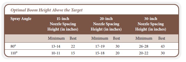
Criterion 7: Nozzle Material
Many of today’s pesticides and fertilizers are abrasive products formulated with inert ingredients such as clay, dry materials suspended in water, and nitrogen (for example, 28 percent and 32 percent). If you consider that brass is too soft for many of the abrasive products used today, most industries rely on three spray tip materials: polymer, stainless steel, and ceramic.
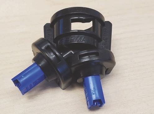
This photo of a dual-pattern asymmetric nozzle with the travel direction moving to the right.
Criterion 8: Single or Dual Spray Pattern
A single spray pattern has been the norm for years. Newer nozzle designs have forward and backward spray patterns. Some operators have observed that double fans are better suited to applications when spray target is vertically oriented and close to the upper part of the canopy.
Criterion 9: One-piece Cap/Nozzle or Separate Nozzle and Cap
Purchasing an all-in-one cap is all about convenience. All-in-one caps also ensure the nozzle is lined up in the body with the proper orientation. If you don’t have a nozzle body turret, then purchasing the cap and nozzle separately might be a better choice given the cap may be able to hold several different spray tips.
Newer caps (whether separate or all-in-one) only allow a certain position for the nozzle to be in position. Each that fan nozzle is slightly off horizontally from the boom direction. As previously discussed, that fan nozzles require 100 percent overlap where the pattern from the adjoining nozzle ends below the nozzle at the target height overlap to get an even volume sprayed across the boom.
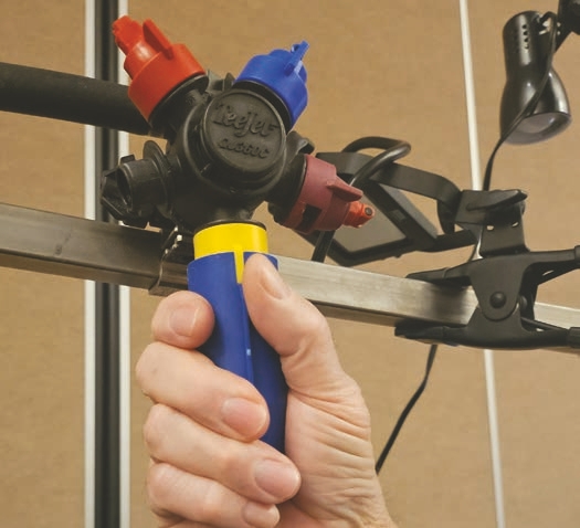
TeeJet® offers a cap installation and removal tool that makes removing nozzles much easier than by hand.
However, if the fan patterns are pointed straight down and parallel to the boom, then the droplets from adjacent fans would collide instead of bypassing one another. Rotating the nozzles just a few degrees (say, 15°) means the droplets are no longer colliding with each other. The lugs built into newer caps (separate and all-in-one) automatically align the nozzles so the opposing spray particles will not collide, but still overlap to form the overall boom pattern.
Make sure to use the right caps for the nozzles. Some caps (such as those used for hollow cone nozzles) can fit most nozzle types; however, they do not automatically offset the spray pattern at 15°. If you use the wrong cap, you would need to manually adjust nozzles one by one along the boom.
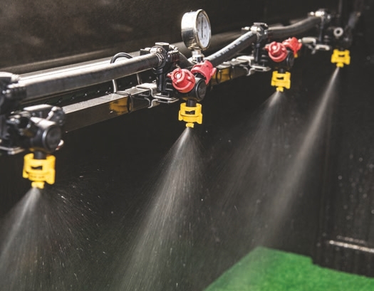
Notice the 15° offset from the boom frame direction between the spray pattern for adjacent nozzles.
Criterion 10: Nozzle Type
All of the previous discussion considered equipment speed, carrier volume, spray angle, droplet distribution, and other factors separately to help explain the inner workings of nozzles. Nozzle manufacturers also provide tables that list their nozzles and the applications each was designed to perform, so applicators have a starting point to optimize their applications.
Working through a Nozzle Chart
Once you select a couple nozzle designs based on your target needs, it will be time to add your specific application information. The following box shows an example of the conditions placed on a nozzle by an applicator. The applicator chooses an extended range that fan nozzle (XR TeeJet®) spray tip to provide good to excellent coverage on weeds. The intended travel speed is 8 MPH, although it may not be possible to maintain this speed at all times. The product label recommends using a nozzle that will provide medium spray droplets.
According to the catalog, this nozzle comes with a 110° fan angle and a stainless tip, which were two of the desired application criteria. Using the following table, how do we go about determining the specific size of the XR Flat fan nozzle that will satisfy the other application criteria given in the box.
We outline the steps to follow for deciding below.
STEP 1. Find the 8 MPH travel speed on top of the table, go down the column, and then identify the sizes of the nozzle that can deliver 15 gallons per acre (GPA). The 110° nozzles that can deliver this rate are: 110 04 (red), 110 05 (brown), and 110 06 (gray).
KNOW WHAT YOU ARE LOOKING FOR BEFORE SEARCHING NOZZLE CATALOG
Before you look at a nozzle catalog, think of the criteria you need to select the right nozzle. Given the desired characteristics in the table below, what nozzle size can best satisfy these spraying conditions?
Criterion
Nozzle type........................ XR Flat Fan
Tip Material....................... Stainless steel preferred
Spray Angle....................... 110°
Overlap.................................. 100%
Nozzle Spacing .............. 20 inches
Speed ..................................... 8 MPH
Application rate............. 15 gallons per acre
Product................................. Herbicide
Droplet Size.......................Medium
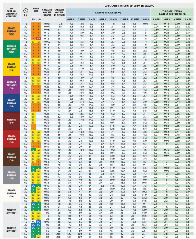
STEP 2. Now, let’s add the next requirement into the selection process, which is for the droplets to be categorized as medium. Which one of the three nozzles from Step 1 are capable of producing medium droplets at the 15 GPA application rate?
• Nozzle 11004: Produces medium droplets at 40 PSI
• Nozzle 11005: Produces medium droplets at close to 30 PSI
• Nozzle 11006: Produces medium droplets at close to 20 PSI
All three nozzles can produce medium droplets while the sprayer is traveling at 8 MPH and delivering an application rate of 15 GPA. However, since we will want to buy only one set of this nozzle type, which one would be a better choice? To answer this question, we need to consider the travel speed range (6-10 MPH) at which the nozzle can be used while delivering medium droplets and meet the 15 GPA requirement.
• Nozzle 11004 (Size 4): Can be operated when the travel speed is 6, 7, or 8 MPH at pressures from 15 to 40 PSI (the label does not show data for 7 MPH, but if the nozzle can satisfy the conditions at 6 MPH and 8 MPH, it should also be acceptable at 7 MPH).
• Nozzle 11005 (Size 5): This nozzle also can be operated when the travel speed is 6,7, or 8 MPH at pressures from 15 to 40 PSI.
• Nozzle 11006 (Size 6): This nozzle can be operated when the travel speed is 8, 9, or 10 MPH at pressures from 20 to 40 PSI (the label does not show data for 9 MPH, but if the nozzle satisfies conditions for 8 MPH and 10 MPH, it should also be acceptable at 9 MPH).
In this case, all three nozzles (sizes 4, 5, and 6) will satisfy all the requirements when they are operated between 20 and 40 PSI. The choice you make will be based on the upper and lower limits of the travel speed you expect the sprayer to operate.
If the travel speed range will be 6 to 8 MPH, sizes 4 or 5 will be better options. However, size 4 will have an edge, because at 6 MPH, the spray pressure with size 6 must be 15 PSI (the lowest operating pressure for this type of a nozzle) to get the desired medium droplet size. It is always a good practice to not operate nozzles at the minimum and maximum pressure settings. If, however, the travel speed range will be 8 to 10 MPH, the size 6 nozzle (110 06) will be the best choice.
A final, but important, suggestion when selecting a nozzle: Before you select a nozzle, it is important to check the manufacturer’s catalog or website for any additional information, such as whether the nozzle is approved for a PWM system.
What Happens If Nozzle Spacing Differs from the Catalog?
It is important to understand that nozzle selection charts usually only show one particular nozzle spacing. In the previous example taken from the TeeJet® catalog, the information in the table for the air induction dual spray pattern was calculated using a 20-inch spacing between each nozzle. Some manufacturers provide tables that also list 15-, 20-, and 30-inch spacings.
Sometimes, they instead provide a conversion factor to help you convert the values in the table for your own boom spacing. If they do not provide a conversion factor for your spacing, you can determine your own conversion factor.
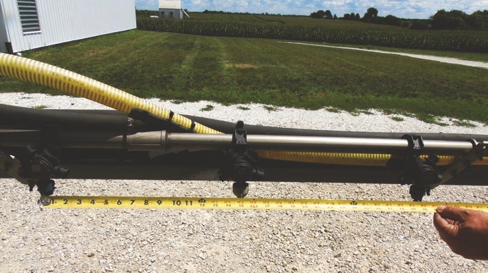
To convert, divide the spacing in the table by the spacing on your boom. For example, the spacing in the table is 20 inches and the spacing on your boom is 15 inches.
So:
Conversion factor = 20/15 = 1.33
You then take the application rate from the table and divide it by the conversion factor to calculate the adjusted rate.
Adjusted rate = 15 ÷ 1.33 = 11.28
This 11.28 GPA rate is the value you will look up in the table for nozzle ratings. There is a second way to determine the rate that some applicators prefer to use to calculate which nozzle meets their needs.
(GPA x MPH x Spacing)/5940 = GPM
GPM: Gallons per minute per nozzle
GPA: Gallons per acre of total spray carrier
MPH: Sprayer travel speed in miles per hour
Spacing: Nozzle spacing on the boom in inches
So, if your desired nozzle output is 15 GPM, the sprayer travel speed is 5 MPH, and the nozzle spacing is 15 inches, your equation is:
(15 x 5 x 15)/5940 = 0.19 GPM
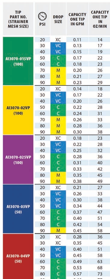
In the table above, look down the column headed Capacity One Nozzle in GPM. The yellow nozzle puts out 0.2 GPM, and at 40 PSI, this nozzle will give a coarse droplet spectrum.
Most major nozzle manufacturers have also developed apps that can provide exact nozzle flow rates required for any given set of application parameters. They can also identify a specific set of nozzle recommendations for the given application parameters. To find these apps, simply visit your preferred application store and search for “spray nozzle calculator” or some other keywords related to nozzle size selection. You may also want search for the name of the nozzle company from which you are interested in buying the nozzles.
However, not all apps are user friendly. They sometimes do not account for droplet size requirements when recommending nozzles. Although the apps and catalog tables may expedite the nozzle selection process, it is best to understand the procedure and the math that nozzle manufacturers use to generate the values they list in tables and use in their apps.
Criteria for Selecting Fertilizer Nozzles
You may recall that manufacturers use clean water to test nozzle output under different pressures. Water weighs 8.34 pounds per gallon, but products like 28 percent and 32 percent UAN weigh approximately 11 pounds per gallon. To spray viscous materials like fertilizers, operators must increase the pressure to compensate for the thicker material and lower flow rate under the same pressure.
To account for the difference in viscosity between water and fertilizer, you want to use a conversion factor (derived by determining the square root of the spray solution’s specific gravity) to make the fertilizer solution equivalent to water.
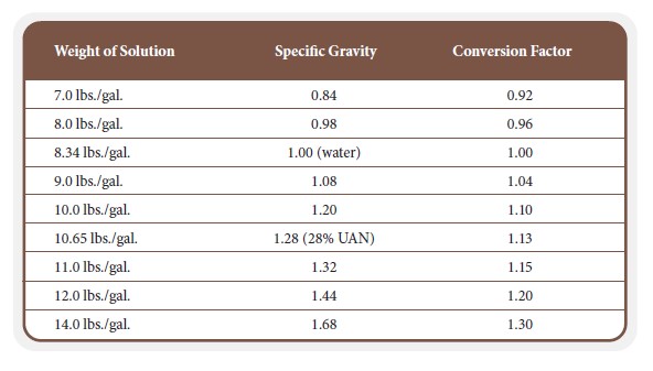
The following table shows conversion factors for a range of solutions. Some catalogs will contain this information.
Assume you want to apply 28 percent UAN at a rate of 15 gallons per acre. Use will use this formula to calculate a rate equivalent to water.
Target GPA of Fertilizer x Conversion Factor = GPA of water
15 (target rate of fertilizer) x 1.13 (conversion factor from table) = 16.95 GPA of water
In other words, to apply 15 GPA of 28 percent UAN, the operator must use the same pressure required to apply 16.95 GPA of water.
Let’s assume that the operator decided to use a StreamJet 3® stream pattern nozzle, the travel speed is 10 MPH, and the operating pressure is 50 PSI. What nozzle would you choose to apply 15 GPA of 28 percent UAN fertilizer, which is equivalent to 16.95 GPA of water? The choices would be the brown nozzle (05) at a pressure between 50 to 60 PSI and the gray nozzle (06) at a pressure between 30 and 40 PSI.
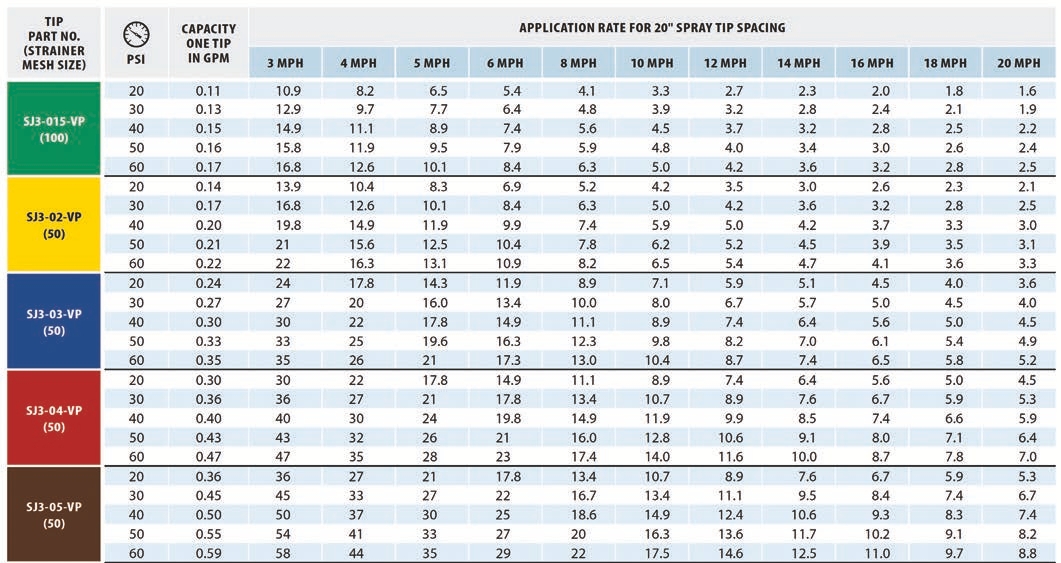
ADJUVANTS MAY INFLUENCE FLOW RATE AND DROPLET SIZES
Nozzle manufacturers’ tables use water as the spray carrier. Consider that we are already adding formulated chemistry to water that carry their own set of inert and active ingredients. Any pesticide product and adjuvant you add to the spray mixture may change the physical properties of the liquid you are spraying. The sprayer is no longer pumping just water out to the nozzles. How does that affect droplet size and flow rate?
Herbicides produce different droplet sizes compared to water. Some herbicides reduce the percentage of fine droplets, but many increase the percent of fines. Glyphosate and glufosinate, with high surfactant load, have shown to move the spray quality as much as two categories lower than shown in the nozzle charts.
Adding adjuvant at rates of 0.5 to 1 percent volume represents a small fraction of the total amount mixed. However, the use of most drift reduction adjuvants will also increase the viscosity of the spray solution. You might notice that when using a drift reduction adjuvant, the sprayer’s operating pressure is a little higher to achieve compared to the same output when no drift reduction adjuvant is used. Other drift reduction/depositon aids do not influence viscosity or spray angle. The bigger effect adjuvants have may be on spray angle and droplet size. Some adjuvants change the physical properties of the liquid and subsequent behavior of the liquid when it atomizes and forms the spray cloud — this will affect droplet size.
Nonionic surfactants often create smaller droplets, because the lower surface tension of the droplets allows the spray to break more easily into smaller droplets. Oils and drift reduction agents (guar and polymers) can create larger droplets and affect spray viscosity. In some cases, adding an adjuvant will change the droplet spectrum to a relatively smaller or larger spectrum. Adjuvants like ammonium sulfate and other water conditioners do not affect either flow rate or droplet size.
In many cases, pesticide manufacturers have already tested how adding adjuvants affects control of the targeted pest. Just be aware that when you are adding products like adjuvants and some herbicide formulations, you may change droplet sizes. Some new herbicides have a specific website with nozzles and adjuvants approved for tank mixtures that will not drastically alter droplet size and product efficacy.

Maintenance and Replacement
There is not a lot of maintenance involved with screens and nozzles. Most of the required maintenance is about being able to detect when a set of nozzles is worn and need to be replaced.
Cleaning Screens and Nozzles
The size of the mesh is normally slightly smaller than the nozzle’s exit orifice, so the mesh catches debris before the nozzles do. Products that easily dissolve in water (like glyphosate) leave no solid particles to clog screens. Conversely, when you apply products that are formulated with clay particles (like atrazine), it is a good practice to check the screens at the end of the day, especially when using dry product formulations. We always recommend that operators follow nozzle manufacturer catalogs to find the correct mesh for nozzle strainers.
If your nozzle tip screens are clogging up, that might be a sign that you need to examine the mixture or the agitation process. It might also be that the partners you used in the mixture are physically incompatible or that you’re using the wrong tip screens for the mix. In other cases, clogged tip screens may indicate that you need to set up the equipment differently. Most spray equipment has a series of inline screens. Reducing the mesh size of these inline screens may help reduce the solid residues plugging up the tip screens and exit orifices.
There is also the possibility that the mixing process is not allowing enough time for the products to disperse completely before they are pumped through the spray components. Keep in mind that using a screen (strainer) that is too small may compromise the flow of certain pesticides that contain particles as part of their formulation and delivery of their active ingredients.
The maintenance required for nozzles is more difficult than screens. Frankly, it is hard to tell when a nozzle is partially plugged when they are behind the sprayer. Rate controllers really do not help when a nozzle or two is completely or partially plugged. If one or two nozzles are not working, the controller will increase the pressure to force more volume out of the remaining nozzles, resulting in an uneven spray distribution along the treated area and probably changes in droplet size.
For these reasons, it is important to know the normal operating pressure when the boom and all nozzles are functioning correctly. If you observe a change in spray pressure when operating the sprayer under normal conditions, you should try to diagnose the cause of the disparity, because it could be a sign of plugged nozzles (increased PSI), or that a spray tip was damaged or fell off (decreased PSI).
Always check the nozzles when flushing the boom. Do a walkaround when spraying water and tank cleaner to check for spray abnormalities. If a nozzle is plugged, shut the sprayer down, use appropriate personal protective equipment, and clean the outside of the nozzle with a nylon-bristle brush to remove caked on soil and mud.
Most of the time, the blockage is a small piece of debris such as sand, rust, or dried chemical inside the nozzle. This means you will have to remove the nozzle body to examine the exit orifice. Remember that the obstruction may not be at the exit orifice but may be in the strainers leading up to the nozzles. Do not insert paper clips, knives, and other objects into exit orifices, because they will damage the nozzle and alter the
pattern. Clean plugged nozzles only with a soft brush, water, or air pressure.
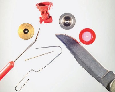
Do not use these objects to clean nozzles. All nozzle materials can be damaged when cleaning them. Small grooves etched into the exit orifice or damage to the walls can change the spray angle, flow rate, and droplet size.
Checking Nozzles for Wear
Solid inerts such as clay particles, dry formulations suspended in the liquid stream, and sand particles in the mixture can abrade the sides of exit orifices, which allows more fluid to flow through.
Worn or damaged spray tips can negatively affect how uniform the spray is distributed across a boom. Instead of an even distribution, worn or damaged nozzles can show peaks and valleys from the fluid collected from nozzle to nozzle. Earlier, we discussed coefficient of variation (CV) as a measure of uniformity during nozzle selection. A brand new, never used nozzle had a CV of 6 percent (100 percent overlap scenario), which is captured using an equipment known as a spray table/patternator as shown in the illustration below.
The blue-colored shapes show the amount of water collected underneath each nozzle. New nozzles (left) show a nearly straight line for the water collected for each nozzle, illustrating a very low and acceptable CV. Notice the discrepancies in the amount of water collected from worn (middle) and damaged (right) spray tips. Instead of an even distribution across the spray boom, some nozzles put out more volume while others less.
NOZZLES WORN FROM USE
As a nozzle naturally wears, the exit orifice opening gets larger. Larger openings increase the flow rate and affect the spray patterns, droplet sizes, and coefficients of variation.
NOZZLES DAMAGED FROM CLEANING
If you use abrasive materials or objects to clean nozzles, it can alter the spray pattern.
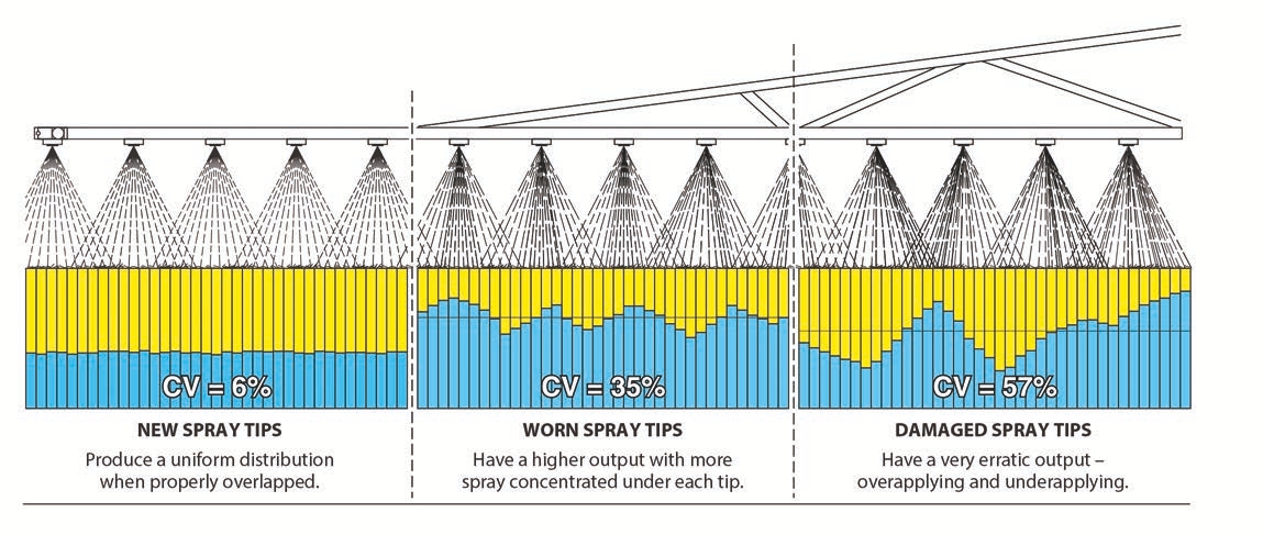
The deformities in the exit orifice are noticeable with the naked eye. In the distribution table above, it is possible to see the uneven distribution instead of an inverted V pattern found on tapered that fan nozzles.
The following three pages are examples of damaged and worn nozzles.
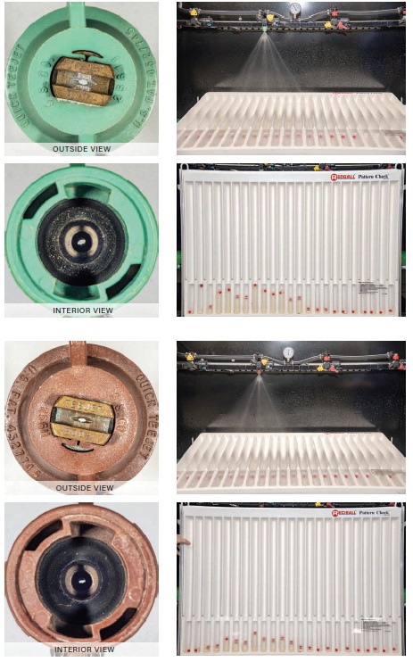
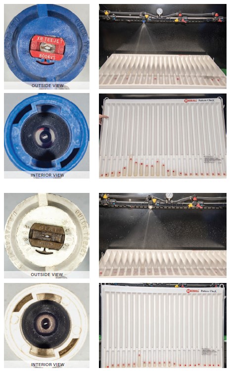
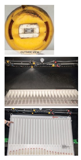
Operators frequently ask, “How long does a set of nozzles last?” While manufacturing processes and materials have greatly improved, all nozzles wear out and need replacing at some point.
The useful life of any nozzle depends on the:
• Quality of the water used to fill the spray tank
• Use of abrasive products
• Use of filters
• Spray pressure
• Nozzle tip material
• Acres applied
• Cleaning practices
• Regularity of cleaning and maintenance, particularly end-of-season maintenance
These and other factors influence how long a set of nozzles will last, but it also means the specific answer to how long nozzles last is not simple. It “all depends.”
There are proven and unproven strategies that are used to evaluate nozzle wear. But evaluating wear is almost impossible, because the human eye cannot detect differences in flow rates between nozzles. Rather than try to predict nozzle lifespans, there are a number of practices that operators have developed to replace nozzles.
Replace Nozzles Annually
Changing nozzles each year is an option that some operators may consider excessive. The principle guiding this strategy is that it is cheaper to replace nozzles than to spend time checking each one. Compared to the costs of the pesticide and fertilizer products, equipment, and labor, the costs of replacing a set of nozzles is a relatively cheap investment. This is an economic decision. Wear Rating: Excellent Strategy!
Replace Nozzles Based on Acres Sprayed
Some operators replace their nozzles after every 25,000 acres sprayed. Larger farms and commercial companies may have to change nozzles yearly. For smaller operations, it will take many years to reach 25,000 acres. This strategy might work for some who know their operations well. All the variables that cause nozzles to wear are specific to each operation. Wear Rating: Moderate to Poor Strategy
Look At Spray Patterns
Some suggest that you turn on the booms and look at spray patterns.
The problem with this approach is that you simply cannot detect differences in flow rates. However, you can sometimes see different patterns, but it may be difficult to see the subtle changes resulting from damaged or worn nozzles. Looking at your spray patterns does have other advantages (for example, noticing clogged tips), so don’t think this activity is not worth your time. Wear Rating: Moderate to Poor Strategy
Compare Old Nozzles to New Ones
It seems that placing two or three new nozzles on a section of the boom and comparing them to the old nozzles should work. However, the human eye cannot see small differences in flow rate, which makes this method suspect. Wear Rating: Poor Strategy!
THE HUMAN EYE IS A POOR WEAR DETECTOR
Your eye is not able to see a 50 percent difference in the flow rate between two nozzles.
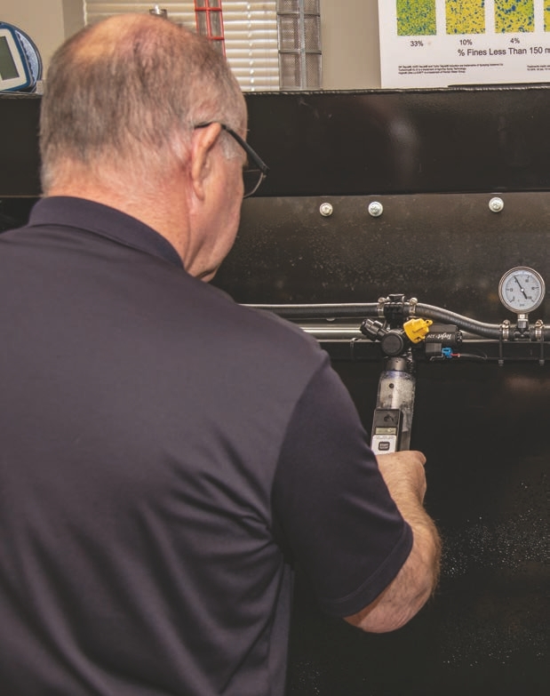
Measure Nozzle Output
The only sure way to tell if a nozzle is worn is to use a collection device and measure the nozzle’s output. We often write about measuring the flow rate of a set of nozzles, but in fact, a turret nozzle assembly may have up to five spray tips. On a 120-foot boom with nozzles spaced 15 inches apart, there are 96 turrets with up to 480 nozzles. This is why you should check nozzles in the winter when there is more time for maintenance. Wear Rating: Excellent Strategy!
A 2022 study measured different methods for determining nozzle flow rates and methods that produced consistent results (sprayers101.com/measure-nozzle-flow).
A calibration tool that stood out in the test was the Innoquest SpotOn Digital Calibrator. This calibration device was consistently accurate, easy to use, and provided results quickly.
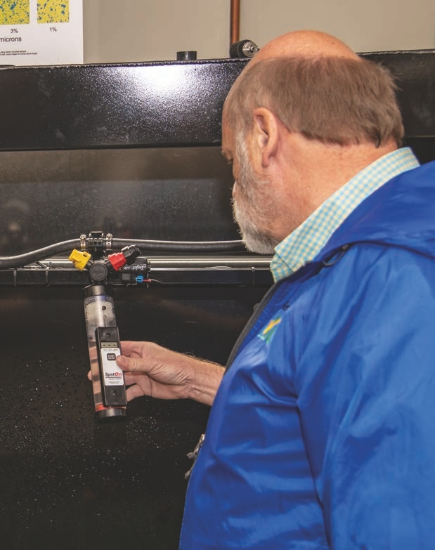
To use the device, you set up the sprayer for a pressure of 40 PSI. Place the device at a slight angle under the nozzle (roughly 15°) to collect the liquid. The meter has a lower and upper sensor. When the liquid reaches the first sensor, it activates the stopwatch inside the system. When the water level gets to the second sensor, it turns off the stopwatch, and the screen displays the flow rate in gallons per minute.
Compare the digital readout value to the output of the nozzle expected at 40 PSI. With worn nozzles, it is typical to replace a nozzle if the flow rate is more than or less than 10 percent of the predicted flow rate listed in the manufacturer’s catalog.
For example, a 04 that fan nozzle at 40 PSI has a theoretical flow rate of 0.4 gallons per minute. Using the 10 percent threshold, the nozzle would be out of specification if the amount of water you collect is at least 0.04 more than (>0.42) or less than (<0.38) the 0.4 gallons per minute. The nozzle would need replacing.
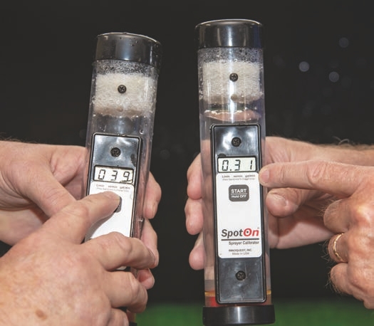
This photo shows the flow rate of water being tested with a SpotOn Sprayer Calibrator. The SpotOn unit on the left displays the flow as ounces per minute (39), while the unit on the right displays gallons per minute (0.31).
A second method to collect the spray output from each nozzle is to collect it in a graduated cylinder for 30 or 60 seconds. For this method, remember the flow rate the value of a new nozzle at a certain pressure. For example, on the table presented the XR 11004 @40PSI must apply 51 fluid ounces in 60 seconds, or 25.5 fluid ounces in 30 seconds. Add up the total amount of water you collect from the sprayer and divide that amount by the number of nozzles. This will give you the average output per nozzle.
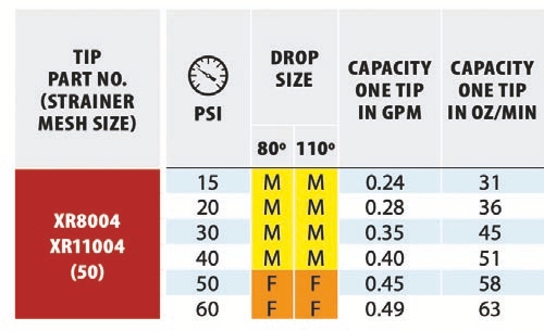
For example, if the sprayer has four nozzles that applied 13.5, 16, 16, and 14.5 fluid ounces, then the average output is 15 fluid ounces per nozzle:
13.5 + 16 + 16 + 14.5 = 60
60 ÷ 4 = 15
Check the nozzle output. If any nozzle varies by more or less than 10 percent of the average output, then there may be a problem with the nozzle. If a nozzle has a lower-than-average output, it may be plugged or have a plugged screen. If a nozzle has a higher-than-average output, it is likely worn out and needs to be replaced.
In the example above, the average output was 15 fluid ounces, so 10 percent is 1.5 fluid ounces. Using 10 percent (1.5 oz) more than or less than the average provides an acceptable range: 13.5 to 16.5 fluid ounces.
Because the output from each nozzle in our example is within this range, none of them needs to be replaced yet. However, the problem with this approach is that you are comparing the nozzles to each other, but not flow rates of individual nozzles. This approach has the disadvantage that one nozzle may have a critical problem that can have a tremendous effect on determining the average flow rate. Thus, the first method described in the previous section would be the preferred approach.
Whether you use a SpotOn, graduated cylinder, or another measuring device, you can only measure the real uniformity of a nozzle if the pressure is the same throughout the spray boom. There can be a difference in the flow rates of nozzles across the boom because of pressure differences from one end of the boom to the next.
EMERGENCY REPAIR KIT IN-FIELD
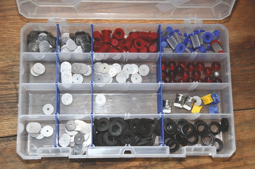
Always have a few replacement nozzles, screens, gaskets, and even a couple of nozzle bodies handy in case you clip a fence post, or your booms get jammed in the dirt. No one wants to be in the field needing to clean a plugged erratically behaving tip. Get the tip out and replace it with a spare new tip.
Clean the nozzles you remove at the shop or in the field at the end of the day after the spraying is done. Use nonabrasive cleaning devices (such as, nylon bristles or compressed air) to clear obstructed nozzles without damaging the orifice shape.
A nozzle may show it is more than 10 percent of the flow rate; however, that nozzle’s output might be influenced by its location on the boom. Nozzles at the center of a boom might be at slightly elevated pressures, so you can expect more volume output. Nozzles near the ends of booms may have lower pressures, reducing output. Simply take those nozzles from the end of the booms and place them in the center to see if the location or wear is resulting in a reduced flow. You can also have a portable pressure gauge to use during the check.
You also can check for even pressure across the boom. The best method is to obtain two liquid-filled stainless- steel gauges and put them on adjoining outlets. Compare the pressures, then switch the nozzles and the outlets, and again compare the pressures.
Then, write on one of the gauges how it compares to the other gauge. Then check pressures on the boom and check the pressure on the boom with the pressure gauge in the cab. Write on the pressure gauge in the cab how it compares to the pressures in the cab. The pressure at the boom is the correct operating pressure. If there are variations in different sections of the boom, then you should examine the plumbing and hoses to see if a more uniform application can be made.
A commonly question asked is: “Is it better to replace a few nozzles that are worn or replace the entire set?” The answer is that this is a personal judgment based on how much you have used the set. If you only have 2,000 acres on them, most will probably replace just the bad ones. If the nozzles have been used a lot over many years, replacing all nozzles is the best choice.
While you could change only nozzles that are outside the 10 percent threshold as a way of saving money, it might not be the best solution. You will need to continually monitor nozzles for wear. It is much easier to put them on as a set and take them off as a set. This will ensure that the wear is consistent across the boom, but you must consider the cost of doing so.
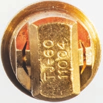
‘VINTAGE’ PARTS KEPT FOR EMERGENCIES
It is common to find in many sprayer cabs or shops a box full of different colored nozzles, different brands and designs, screens, tips, and plumbing pieces. Why?
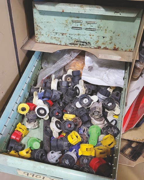
The answer is always, “I might need one in an emergency.” But when was the last time you actually dug something out of the box and used it on the sprayer?
It is better to discard of these parts properly instead of saving them for just in case. They are no longer good, which is why they ended up in the junk box or drawer. They did their job, so discard them. If you leave them sitting around, you might be tempted to put them back on or confuse them with new nozzles.
Did we mention that you should throw away the nozzles that are no longer being used?
The Unsung Heroes of Liquid Applications


A BETTER RULER
Science gives operators greater precision when spraying…but it can all be brought down if the nozzle doesn’t perform.
With the many advances in pesticide application equipment, it seems that nozzles have been relegated to “old” technology — they are little more than pieces of plastic or metal attached to booms. However, all the bells and whistles that add precision to applications are of little value unless the simple nozzle performs in a desired manner.
A pesticide or fertilizer is only as good as the method in which it is applied. Ultimately, this comes down to the spray nozzle. All spray clouds may appear similar - they just create a spray mist, right? However, there are important parameters in that spray cloud. They may not be visible to the naked eye, but they can have an impact on spray pattern uniformity and pesticide efficacy.
Newer nozzle designs have definitely changed as the portfolio of pesticides and other products has steadily grown. With equipment and pesticides becoming more expensive and sophisticated, we must expect nozzles to hold up their end of the application process. Since the 1940s, nozzles, just like equipment and pesticides, have witnessed steady improvements in designs and applications.
These advances include:
• Nozzles designed for specific applications
• Consistent spray patterns and droplet size spectrums from one nozzle to the next
• Standards in nozzle manufacturing
• Technological advances in the nozzle body
• Better materials used in nozzle tip construction
• Techniques that can easily measure the distribution of specific droplet sizes
• Techniques that can control nozzle flow rate at variable speeds
• New spray angles and spray patterns that fit different targets
• Precise flow rate control
• Consistent nozzles with the same characteristics - flow rate, droplet size, spray angle
• Technologies that reduce off-target drift
Today’s nozzles would not have made these rapid advances without modern equipment that could accurately measure the spectrum of droplets a nozzle produces.
HAVING CHOICES IS IDEAL
There is a reason to have all these different nozzle types in the market. Operators need to understand each application to select the right nozzle.
You should ask:
• What is your target, and where is it located?
• Which crop, and at which development stage, will the application take place?
• What type of product is going to be applied? Is it a contact or a systemic product?
• What are the ideal weather conditions for applying this product?
• What is the correct droplet size for this product application?
• What is the necessity of drift control?
What we know today is that a better understanding of how these and other factors interact with each other is no longer optional if the pesticide product applications are to work as designed.
The ability to measure and quantify droplet sizes allowed the nozzle manufacturing industry to adapt their products to meet the needs of specific pesticide chemistries. The need for manufacturers to quantify and meet their customers’ needs prompted continued research on finding the droplet sizes, patterns, and coverages that are needed to make products work as intended.
Today’s analytical tools allow researchers to measure the performance of nozzles, including atomization mechanism, spray angle, overlap, droplet size, and drift potential. With all these advances, applicators should be aware that they should use different nozzles for different types of applications. The one-size-fits-all mentality no longer applies in the pesticide application industry.
Pesticide applications determine returns on investment of time and materials. It is not only what you put in the spray tank that determines the level of control your application achieves — how the product is applied influences application, too. It is more important today than in years past to know what a specific nozzle does and how it does it, because pest control is expensive.
Precision farming, post-emergence application, minimum tillage, and precision planting have evolved and have become a much larger part of farming activities. Nozzles are an integral part of how modern farming is done today and will be in the future. The nozzle is the last point at which any applicator has control over the application, so it is critical to get that right!
KEY TAKE HOME MESSAGES
• Pesticides and nozzles are two wheels of the same cart; each must work simultaneously and in tandem to achieve a successful spray application.
• One nozzle doesn’t fit every application. It is important to change nozzles to optimize pesticide applications.
• Plan ahead to get the right nozzle for the application.
• Don’t overthink or overanalyze nozzle selection. It is a rather straightforward process, so let the science work for you.
Acknowledgements
Thanks to Dawn Minns for graphic design and Adduci Studios for illustrations. We also thank TeeJet Technologies, Greanleaf Technologies and Pentair Hypro for permission to reproduce some of the charts and graphics from their catalogs in this publication. Thanks also to the following individuals who provided valuable comments and suggestions that improved this publication:
Thomas Butts, University of Arkansas
Leandro Cordova, Corteva AgriScience
Gary Cornell, Asmark Institute
Jason Deveau, Ontario Ministry of Agriculture, Food and Rural Affairs
Joe Gednalske, WinField United
Joseph Ikley, North Dakota State University
Robert Klein, University of Nebraska
Greg Kruger, Rosen’s
Jesaelen Moraes, Blue River Technology
Jeff Nagel, Ceres Solutions
Disclaimer
This publication is intended for educational purposes only. The authors’ views have not been approved by any government agency, business, or individual and cannot be construed as representing a perspective other than that of the authors. The publication is distributed with the understanding that the authors are not rendering legal or other professional advice to the reader, and that the information contained herein should not be regarded or relied upon as a substitute for professional consultation. The use of the information contained herein constitutes an agreement to hold the authors, companies, or reviewers harmless for liability, damage, or expense incurred as a result of reference to or reliance upon the information provided. Mention of a proprietary product or service does not constitute an endorsement by the authors or their employers. Descriptions of specific situations are included only as hypothetical case studies to assist readers of this publication and are not intended to represent any actual person, business entity, or situation. Reference in this publication to any specific commercial product, process, or service, or the use of any trade, firm, or corporation name is for general informational purposes only and does not constitute an endorsement, recommendation, or certification of any kind by Purdue University. Individuals using such products assume responsibility that the product is used in a way intended by the manufacturer and misuse is neither endorsed nor condoned by the authors nor the manufacturer.
Reference in this publication to any specific commercial product, process, or service, or the use of any trade, firm, or corporation name is for general informational purposes only and does not constitute an endorsement, recommendation, or certification of any kind by Purdue Extension. Individuals using such products assume responsibility for their use in accordance with current directions of the manufacturer.
Find out more at
THE EDUCATION STORE
edustore.purdue.edu